
Image forming apparatus

a technology of image forming and forming equipment, which is applied in the direction of digitally marking record carriers, visual presentation using printers, instruments, etc., can solve the problems of increasing maintenance costs and excessive processing frequency for correction of main scanning scaling errors, and achieve adequate correction of positional errors

Inactive Publication Date: 2013-05-02
RICOH KK
View PDF3 Cites 9 Cited by
  • Summary
  • Abstract
  • Description
  • Claims
  • Application Information

AI Technical Summary

Benefits of technology

The present invention is about an image forming apparatus that can correct positional errors caused by using light emitting elements with different lengths. The invention ensures that the positional error correction is effective even when different light emitting element arrays are used. This helps to improve the quality of the image formed by the apparatus.

Problems solved by technology

However, light emitting elements of each color disposed on the photoreceptor have different lengths, because the main scanning scaling is different originally, the processing frequency required for correction of the main scanning scaling error is excessive.
Accordingly, light emitting elements having the same length has come to be used, but the length of all the light emitting elements needs to be adjusted, thereby increasing the cost for maintenance.

Method used


Image

  • Image forming apparatus
  • Image forming apparatus
  • Image forming apparatus

Examples


Embodiment Construction

[0029]Preferred embodiments of a color image forming apparatus according to the present invention will now be described in detail with reference to the accompanying drawings.

[0030]A structure and operation of an image forming apparatus according to one embodiment of the present invention will now be described.

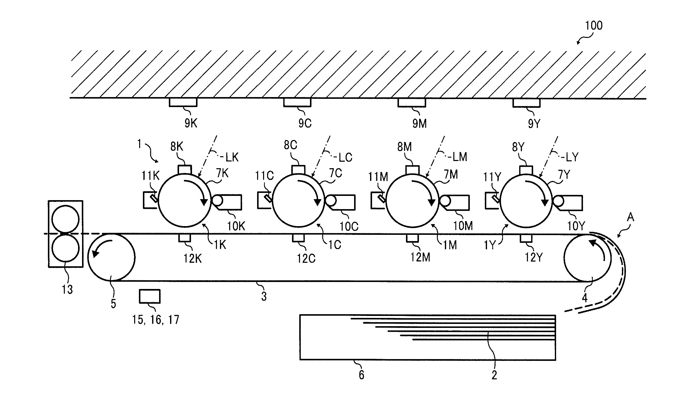
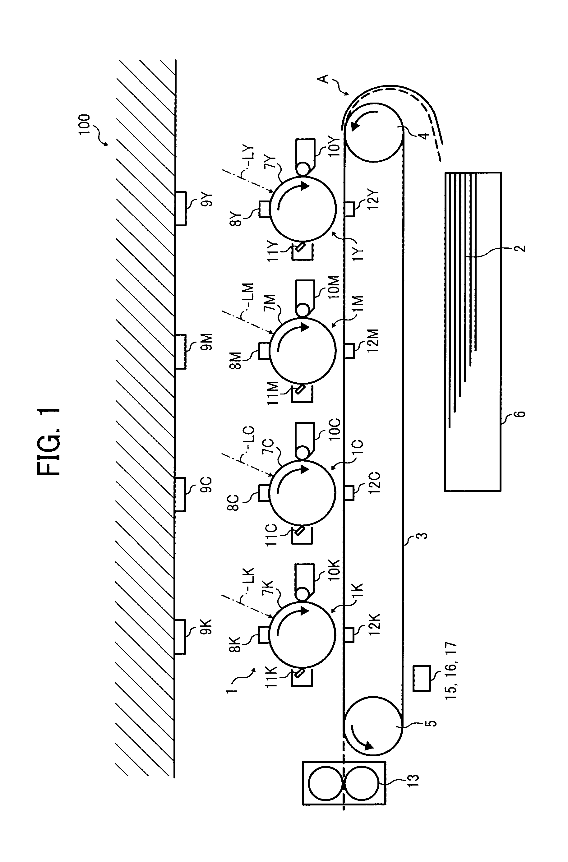
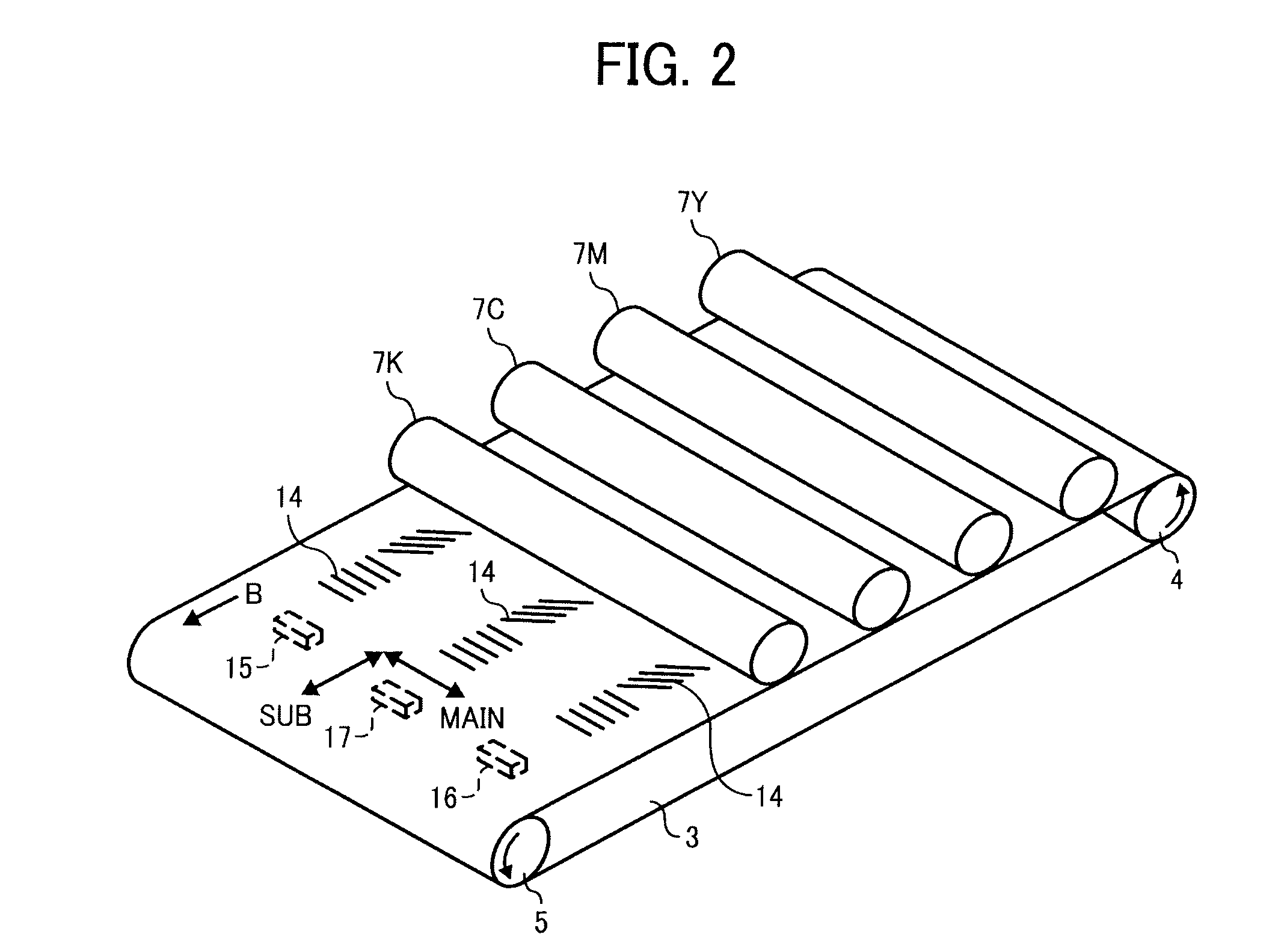
[0031]FIG. 1 is a front view of image forming units and a transfer belt illustrating a principle of image formation by a color image forming apparatus 100, which forms an image on a transfer medium by an electrophotographic method. As illustrated in FIG. 1, the image forming apparatus 100 includes photoreceptors 7K, 7M, 7C, and 7Y; image processing units 1K, 1M, 1C, and 1Y; and an intermediate transfer belt 3. Each suffix of K, M, C, and Y represents a color of black, magenta, cyan, and yellow. The image forming apparatus 100 forms an electrostatic latent image on each photoreceptor, and thereafter, each image processing unit disposed in line along the intermediate transfer bel...


PUM


Abstract

An image forming apparatus includes: Photoreceptors; an image carrier; a plurality of light emitting element arrays each configured to emit a light beam to a corresponding one of the photoreceptors independently; an angle adjustment unit to adjust a mounting angle of the light emitting element arrays to a frame of the image forming apparatus; a pattern forming unit to form a positional error correction pattern of each color on the image carrier; a optical detector to detect the correction pattern formed on the image carrier; a positional error calculation unit to calculate a printing skew error and a main scanning scaling error of the light emitting element arrays based on the correction pattern detected by the optical detector; a skew correction unit to correct the printing skew error detected by the positional error calculation unit; and further a main scanning scaling error correction unit.

Description

CROSS-REFERENCE TO RELATED APPLICATION[0001]The present application claims priority from Japanese patent application number 2011-239495, filed on Oct. 31, 2011, the entire contents of which are incorporated by reference herein.BACKGROUND OF THE INVENTION[0002]1. Field of the Invention[0003]The present invention relates to an image forming apparatus in which a plurality of images are formed on an image carrier in a superposed manner to form a full-color image and the image formed on the image carrier is transferred to a paper medium, and in particular, relates to an image forming apparatus capable of correcting a color shift of an image forming unit when the above image forming process is performed.[0004]2. Description of the Related Art[0005]Conventionally, due to an acute demand for a color image forming apparatus capable of printing images at a higher speed, a color image forming method which is called a tandem method has become the main type of the high speed image forming appara...

Claims


Application Information

Patent Timeline
IPC IPC(8): G06K1/00
CPCG03G15/00G06K1/00G03G15/5058
Inventor SHUKUYA, YUICHIRO
Owner RICOH KK
Learn More