spectrometer
- Summary
- Abstract
- Description
- Claims
- Application Information
AI Technical Summary
Benefits of technology
Problems solved by technology
Method used
Image
Examples
first embodiment
[0041]Hereinafter, a first embodiment of the invention will be described with reference to the accompanying drawings.
[0042]Configuration of Spectrometer
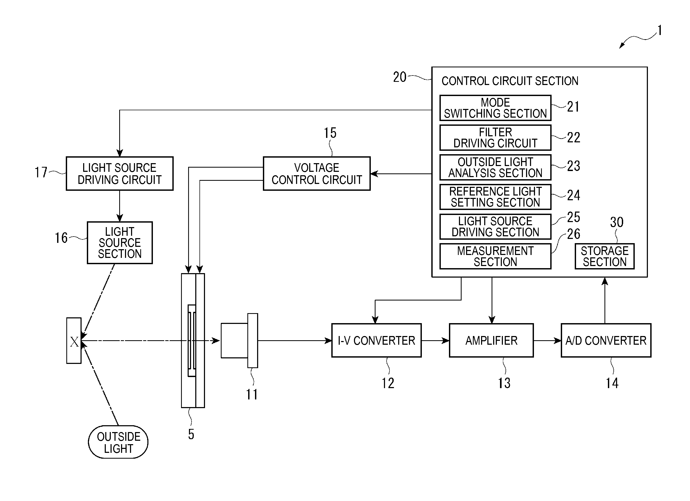
[0043]FIG. 1 is a block diagram illustrating a schematic configuration of a spectrometer according to the embodiment of the invention.
[0044]A spectrometer 1 is a device that acquires the amount of light (light intensity) of each wavelength in light to be measured which is reflected from an object X and measures the spectral characteristics of the light to be measured, and, particularly, measures the spectral characteristics covering a visible light region to a near-infrared light region.
[0045]As shown in FIG. 1, the spectrometer 1 includes a variable wavelength interference filter 5, a detector 11 (detection section), an I-V converter 12, an amplifier 13, an A / D converter 14, a voltage control circuit 15, a light source section 16, a light source driving circuit17, and a control circuit section 20 (control section).
[0046]Configuratio...
second embodiment
[0139]Next, a second embodiment of the invention will be described with reference to the accompanying drawings. Meanwhile, in the description of the following embodiment, the same components as those in the first embodiment are designated by the same reference numerals and signs, and the description thereof will be omitted or simplified.
[0140]In the above-mentioned first embodiment, an example has been illustrated in which the outside light analysis section 23 analyzes the spectral characteristics of the outside light in a state where reference light irradiation is stopped. On the other hand, the embodiment is different from the above-mentioned first embodiment, in that the outside light analysis section determines whether the amount of the outside light in each wavelength is larger than a predetermined value in a state where reference light irradiation is performed from the light source section 16.
[0141]FIG. 9 is a diagram illustrating a schematic configuration of a spectrometer ac...
third embodiment
[0162]Next a third embodiment of the invention will be described with reference to the accompanying drawings.
[0163]In the above-mentioned first embodiment, the outside light analysis section 23 analyzes the spectral characteristics of the outside light on the basis of the output value acquired by the detector 11. In the second embodiment, the outside light analysis section 23 analyzes whether the amount of the outside light is equal to or more than the specified value on the basis of the output value acquired by the detector 11.
[0164]On the other hand, in the embodiment, an outside light sensor that detects only the outside light is separately included, and the outside light analysis section detects the outside light on the basis of a detection signal from the outside light sensor.
[0165]FIG. 11 is a diagram illustrating a schematic configuration of a spectrometer 1B according to the third embodiment.
[0166]As shown in FIG. 11, the spectrometer 1B of the embodiment includes a variable...
PUM
 Abstract
Description
Claims
Application Information
 - R&D
- Intellectual Property
- Life Sciences
- Materials
- Tech Scout
- Unparalleled Data Quality
- Higher Quality Content
- 60% Fewer Hallucinations
Browse by: Latest US Patents, China's latest patents, Technical Efficacy Thesaurus, Application Domain, Technology Topic, Popular Technical Reports.
© 2025 PatSnap. All rights reserved.Legal|Privacy policy|Modern Slavery Act Transparency Statement|Sitemap|About US| Contact US: help@patsnap.com


