
Antenna radiating element

a technology of radiating elements and antennas, applied in the direction of antenna details, polarised antenna unit combinations, antennas, etc., can solve the problems of increasing the number of parts involved in the manufacture of antennas, reducing the overall performance of antennas, and increasing the number of parts needed, so as to improve the beam width

Active Publication Date: 2013-05-02
RFS TECH INC
View PDF5 Cites 6 Cited by
  • Summary
  • Abstract
  • Description
  • Claims
  • Application Information

AI Technical Summary

Benefits of technology

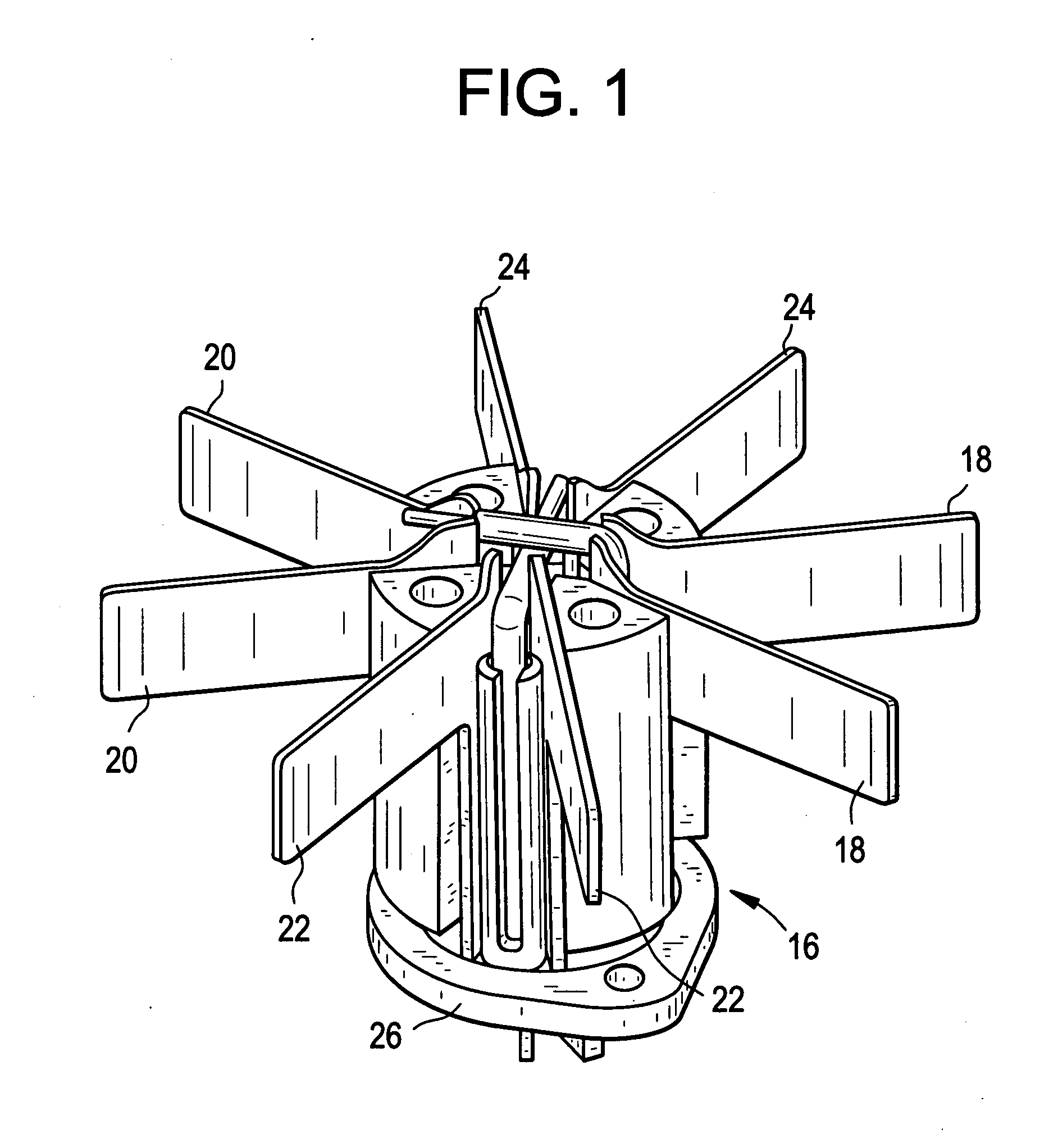
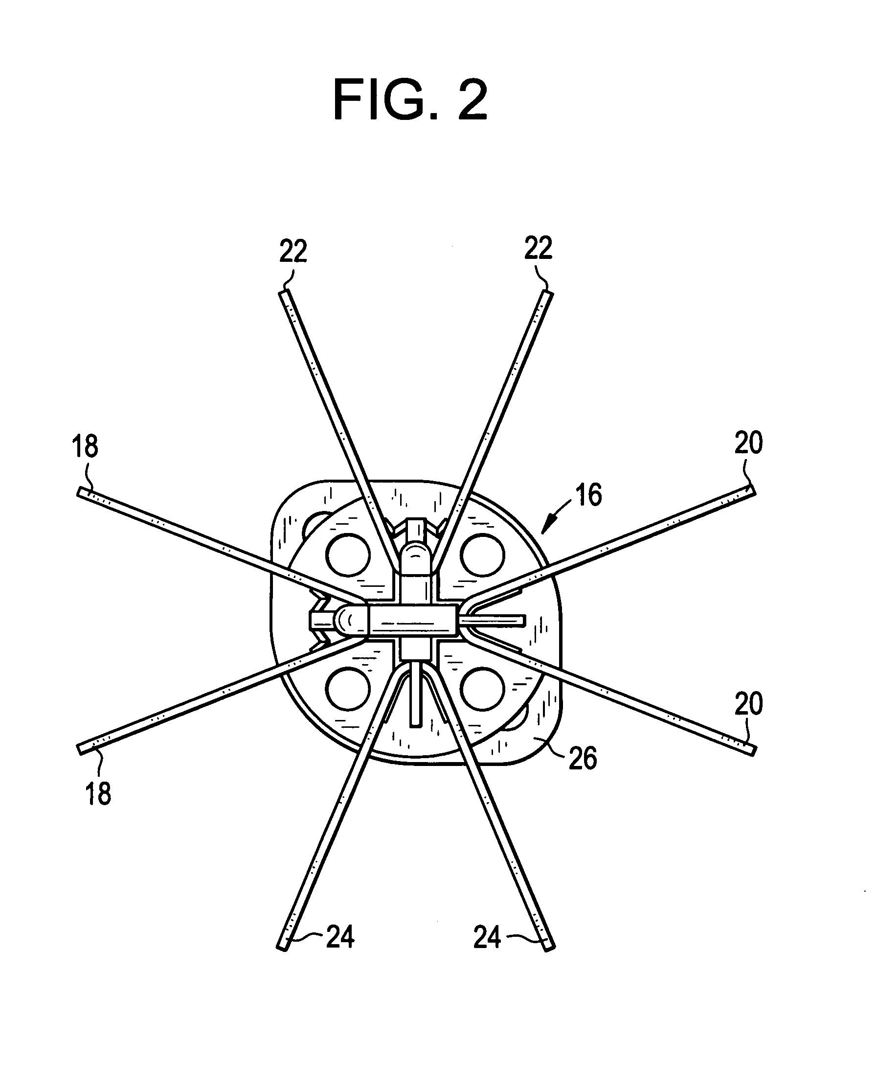
This patent is about a way to make antennas with wider beams. It uses a shroud or baffle design that helps improve the antenna's performance.

Problems solved by technology

Building antenna using this approach is undesirable, however, because creating the dual polarization effect with single linear polarized elements increases the labor cost and the number of parts involved in the antenna's manufacture, while reducing its overall performance.
The drawback to using these conventional coupling structures with the antennae and dipoles described above is that they increase the number of parts needed to construct the antenna, thereby generating undesired intermodulation distortions.
In addition, manufacturing these panel antennae with dipoles that include numerous radiating elements often requires numerous solder joints and screw connections.
The total number of parts required in such panel antennae, in addition to the cost of their assembly, makes them unsuitable for mass-production.
In addition, solder, screws, and similar types of attachments between parts not only add to the manufacturing time and labor cost, but also generate undesired intermodulation distortions as well.
But using the air dielectric transmission lines that are common in conventional coupling structures creates distortions in the signal fed to and from the reflector.
In these circumstances, it is prohibitively expensive and difficult to achieve the desired isolation, meaning that the antenna cannot be configured such that one port is used for transmission and the other port for reception.
In conventional antennas (e.g., butter fly design antennas and Four Square dipole elements), regular dipole antennas have issues with cross polarization and isolation between the same band elements and different bands for multi band and higher beam width antennas.
Minimizing cross polarization and isolation using conventional techniques are expensive and time consuming.
Further, development procedures and production of conventional antennas is expensive.

Method used


Image

  • Antenna radiating element
  • Antenna radiating element
  • Antenna radiating element

Examples


Embodiment Construction

[0025]While example embodiments are capable of various modifications and alternative forms, embodiments thereof are shown by way of example in the drawings and will herein be described in detail. It should be understood, however, that there is no intent to limit example embodiments to the particular forms disclosed, but on the contrary, example embodiments are to cover all modifications, equivalents, and alternatives falling within the scope of the claims. Like numbers refer to like elements throughout the description of the figures.

[0026]Before discussing example embodiments in more detail, it is noted that some example embodiments are described as processes or methods depicted as flowcharts. Although the flowcharts describe the operations as sequential processes, many of the operations may be performed in parallel, concurrently or simultaneously. In addition, the order of operations may be re-arranged. The processes may be terminated when their operations are completed, but may al...


PUM

PropertyMeasurementUnit
conductiveaaaaaaaaaa
non-conductive aaaaaaaaaa
dimensionaaaaaaaaaa

Abstract

The antenna radiating element includes an antenna configured to transmit a signal having one or more measurable characteristics and a shroud surrounding the antenna and configured to change the one or more measurable characteristics.

Description

BACKGROUND OF THE INVENTION[0001]1. Field[0002]Embodiments relate to base-station antennae for use in mobile communication systems.[0003]2. Related Art[0004]Dipole antennae are common in the communications industry, and conventional structures, including half-wavelength dipoles with “bow tie” structures and “butterfly” structures, are described in several known publications.[0005]In particular, panel base-station antennae, such as those used in mobile communication systems, rely heavily on dual polarization antennae. In many cases, these antennae are constructed using single linear polarized elements, grouped in such a way that creates dual polarization. In this case, two separate arrays of radiating elements are required to radiate on both polarizations.[0006]Building antenna using this approach is undesirable, however, because creating the dual polarization effect with single linear polarized elements increases the labor cost and the number of parts involved in the antenna's manuf...

Claims


Application Information

Patent Timeline
Patent Type & Authority Applications(United States)
IPC IPC(8): H01Q21/26H01P11/00
CPCH01Q1/246Y10T29/49016H01Q21/24H01Q19/10H01Q1/24
Inventor KATIPALLY, RAJASTANEK, ANDRZEJPOWELL, CHUCK
Owner RFS TECH INC
Learn More