Rear-mounted aerodynamic structures for cargo bodies

Inactive Publication Date: 2013-05-02
STEMCO LP
View PDF6 Cites 58 Cited by
  • Summary
  • Abstract
  • Description
  • Claims
  • Application Information

AI Technical Summary

Benefits of technology

The patent describes an aerodynamic structure that improves the airflow of a cargo body, such as a truck or trailer. The structure includes an upper panel and side panels that can be opened and closed to control the airflow. The top panel is connected to the side panels through a linkage, so that the side panels move in a coordinated manner. The structure also includes a swingarm that connects the upper panel to the cargo body door, so that the panels move in a coordinated manner. The upper panel can be automatically opened or closed based on the resistance of the cargo body. The aerodynamic structure helps to reduce fuel consumption, improve cargo safety, and avoid damage to the cargo body.

Problems solved by technology

The flat, projecting front face of a cargo body is a substantial source of drag, above the cab roof.
To improve the aerodynamics of a truck or trailer cargo body by reducing drag, several solutions have been provided that focus on trucks having swinging doors, which are not always readily applicable to cargo bodies having rolling doors.
Most attempts to provide aerodynamic structures that integrate with the structure and function of the rear cargo doors of a truck have been unsuccessful and / or impractical to use and operate.
Such rear aerodynamic structures are typically large and difficult to remove from the rear so as to access the cargo doors when needed.
However, aerodynamic structures that swing upwardly require substantial strength or force to be moved away from the doors, and also require substantial height clearance above an already tall cargo body.
While this requires less force to move, it also requires substantial side clearance—which is generally absent from a closely packed, multi-truck loading dock.
In such an environment, side-projecting or top-projecting fairings would invariably interfere with operations at the loading dock.
Another challenge to providing a rear aerodynamic structure is the prompting of a user to deploy the aerodynamic structure at the appropriate time.
In particular, if this is performed too late, it may not have the desired effectiveness on improving fuel efficiency and aerodynamic drag, and if performed at lesser speeds, the aerodynamic structure may be unnecessary.

Method used


Image

  • Rear-mounted aerodynamic structures for cargo bodies
  • Rear-mounted aerodynamic structures for cargo bodies
  • Rear-mounted aerodynamic structures for cargo bodies

Examples


Embodiment Construction

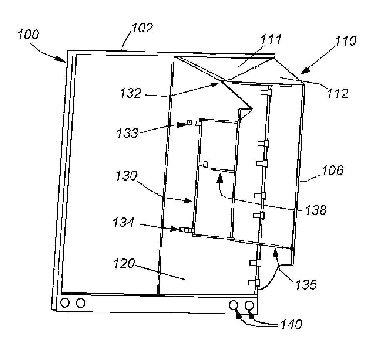
[0082]A rear-mounted aerodynamic structure for securing to a cargo body includes a three- or four-sided structure having a deployed position for assisting in improving aerodynamic efficiency of the cargo body. The cargo body can be the body of a trailer of a tractor-trailer vehicle or trailer towed behind a vehicle such as a truck. It can comprise a trailer body or other cargo body well-known in the art. In an illustrative embodiment, a spoiler “flow keeper” is mounted to a top surface of the rear of the cargo body, as an additional aerodynamic structure or as a standalone spoiler for cargo bodies. The three- or four-sided rear-mounted aerodynamic structure can comprise any of a variety of illustrative embodiments shown and described herein, as well as additional aerodynamic structures as shown and described herein.

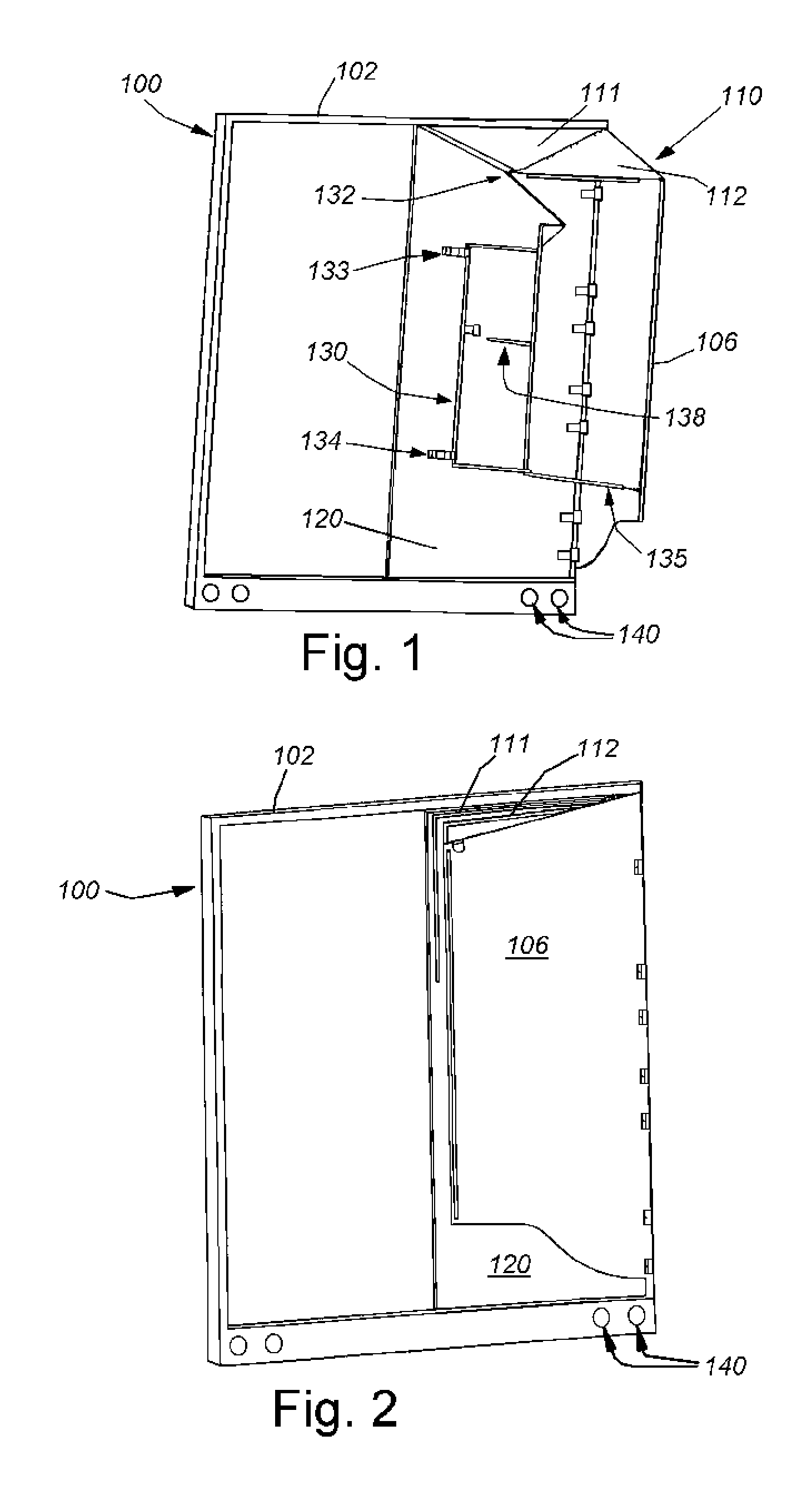
[0083]I) Rear-Mounted Aerodynamic Structure Including Upper Panel and Side Panel

[0084]Reference is made to FIG. 1 showing a rear perspective view of a single door-mounted...


PUM


Abstract

A rear-mounted aerodynamic structure for securing to a cargo body includes a three- or four-sided structure having a deployed position for assisting in improving aerodynamic efficiency of the cargo body. The cargo body can be the body of a trailer of a tractor-trailer vehicle or trailer towed behind a vehicle such as a truck. It can comprise a trailer body or other cargo body well-known in the art. A spoiler “flow keeper” mounted to a top surface of the rear of the cargo body, as additional aerodynamic structures or as a standalone spoiler for cargo bodies. The three- or four-sided rear-mounted aerodynamic structure can comprise any of a variety of illustrative embodiments shown and described herein.

Description

RELATED APPLICATIONS[0001]This application claims the benefit of U.S. Provisional Application Serial No. 61 / 552,198, filed Oct. 27, 2011, entitled REAR-MOUNTED AERODYNAMIC STRUCTURES FOR CARGO BODIES, the entire disclosure of which is herein incorporated by reference.FIELD OF THE INVENTION[0002]The present invention relates to aerodynamic structures that are secured to the rear of cargo bodies, for example, on trucks or trailers, and other aerodynamic structures to improve airflow around the cargo body.BACKGROUND OF THE INVENTION[0003]Trucking is the primary mode of long-distance and short-haul transport for goods and materials in the United States, and many other countries. Trucks typically include a motorized cab in which the driver sits and operates the vehicle. The cab is attached to a box-like cargo section. Smaller trucks typically include an integral cargo section that sits on a unified frame which extends from the front wheels to the rear wheel assembly. Larger trucks often ...

Claims


Application Information

Patent Timeline
IPC IPC(8): B62D35/00
CPCB62D35/001
Inventor SMITH, ANDREW F.GROSSMANN, JEFFREY J.HINRICHER, COURT S.CHOLNOKY, ROBERT R.
Owner STEMCO LP
Why Eureka
Try Eureka