
Strain Isolation Layer Assemblies and Methods

a technology of isolation layer and assembly method, which is applied in the direction of energy-efficient board measures, pv power plants, transportation and packaging, etc., can solve the problems of brittleness and limited use of known photovoltaic solar cells or solar panel arrays, the connection or mounting of known photovoltaic solar cells or solar panels to structures, and the strain level of photovoltaic solar cells or solar panel arrays being forced to approximate the same strain level. , to achieve the effect o

Active Publication Date: 2013-05-02
THE BOEING CO
View PDF7 Cites 19 Cited by
  • Summary
  • Abstract
  • Description
  • Claims
  • Application Information

AI Technical Summary

Benefits of technology

The patent describes improved assemblies and methods for connecting solar cells and panels to structures and reducing strains on them. These improvements may offer advantages over existing methods. One example is a strain isolation layer that is placed between a rigid solar layer and a flexible surface, such as an aircraft wing, to reduce strains on the solar layer. The strain isolation layer has a unique configuration that includes both vertical rigidity and horizontal shear flexibility. This layer can be attached using an added layer between the strain isolation layer and the rigid solar layer. Overall, the patent provides technical solutions for protecting and preserving the integrity of solar cells and panels in various applications.

Problems solved by technology

However, the connection or mounting of known photovoltaic solar cells or solar panels to structures, such as solar powered UAVs or other aircraft and vehicles, or terrestrial and space-based structures, may present difficulties.
Known photovoltaic solar cells or solar panel arrays may be brittle and may have limited use if exposed to excessive levels of strain.
Thus, the direct connection or mounting of thin photovoltaic solar cells or solar arrays to a vehicle, such as an aircraft or aerial vehicle, may result in the photovoltaic solar cells or solar arrays being forced to approximate the same strain levels as the aircraft or aerial vehicle structure.
In turn, this may result in the photovoltaic solar cells or solar arrays ceasing to function properly.
However, unsupported thin solar cells or solar panel arrays may buckle when subjected to compressive strains.
Significant buckling may occur even at very low strain levels.
Such buckling may disrupt or prevent laminar flow affecting flight characteristics of the aircraft or aerial vehicle or may damage such unsupported solar cells or solar panel arrays.
Such wrinkling may disrupt or prevent laminar flow or may damage such solar cells or solar panel arrays.
However, with such known assembly and method, the gaps and connections between the photovoltaic solar cells may disrupt laminar flow.
Moreover, with such known assembly and method, the cost of mounting or connecting numerous individual photovoltaic solar cells to the wing or other surface of an aircraft or aerial vehicle or other terrestrial and space-based structures, may increase due to increased time, complexity and labor that may be required to mount or connect such solar cells.
Finally, with such known assembly and method, forces exerted by the electrical connection between the photovoltaic solar cells on the solar cells themselves may result in the solar cells being thicker and heavier than needed.
However, with such known assembly and method, the aircraft wing structure may require reinforcement to limit strain in service to levels below that which may be tolerated by the photovoltaic solar cells.
This may result in a substantial increase in the weight of the aircraft wing structure.
Moreover, with such known assembly and method, solar cells may be difficult to remove and replace.
Thus, a damaged solar cell may result in the entire aircraft wing being scrapped or may result in a costly repair process.
Finally, with such known assembly and method, it may not be known until after the aircraft wing is finished whether the solar cells may be working properly.
If the solar cells are not working properly after assembly, for example, if the solar cells are damaged during assembly, this may result in a costly repair process.

Method used


Image

  • Strain Isolation Layer Assemblies and Methods
  • Strain Isolation Layer Assemblies and Methods
  • Strain Isolation Layer Assemblies and Methods

Examples


Embodiment Construction

[0050]Disclosed embodiments will now be described more fully hereinafter with reference to the accompanying drawings, in which some, but not all of the disclosed embodiments are shown. Indeed, several different embodiments may be provided and should not be construed as limited to the embodiments set forth herein. Rather, these embodiments are provided so that this disclosure will be thorough and complete and will fully convey the scope of the disclosure to those skilled in the art.

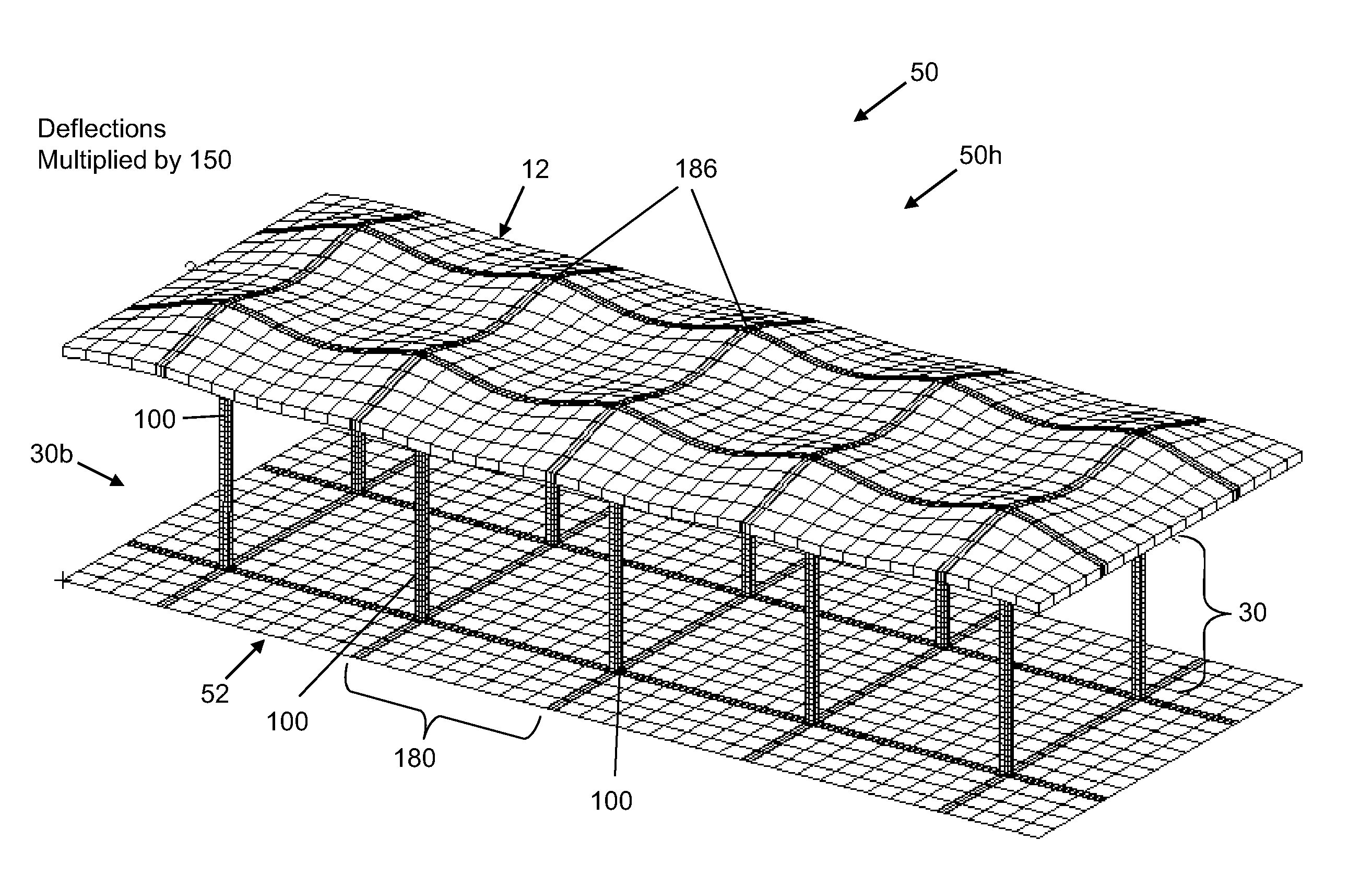
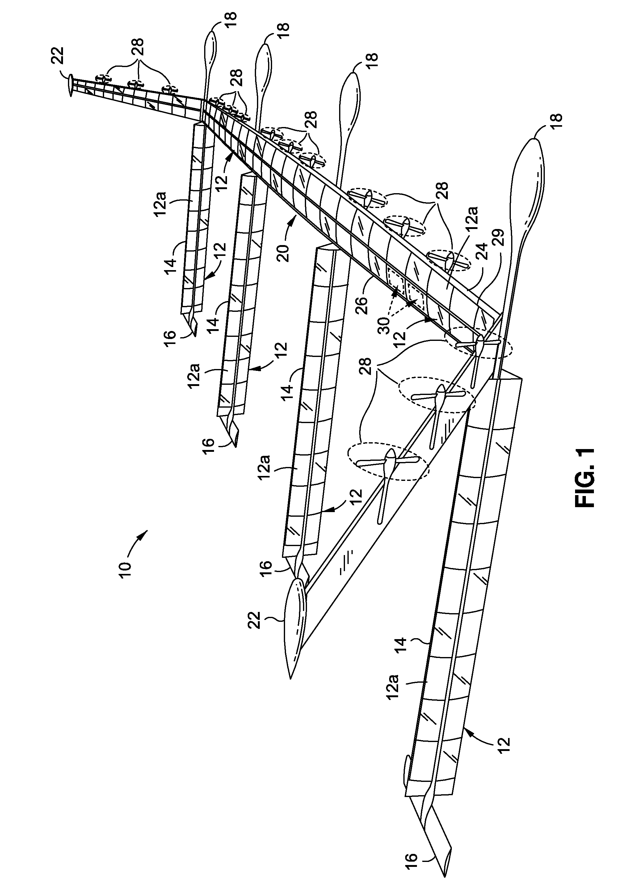
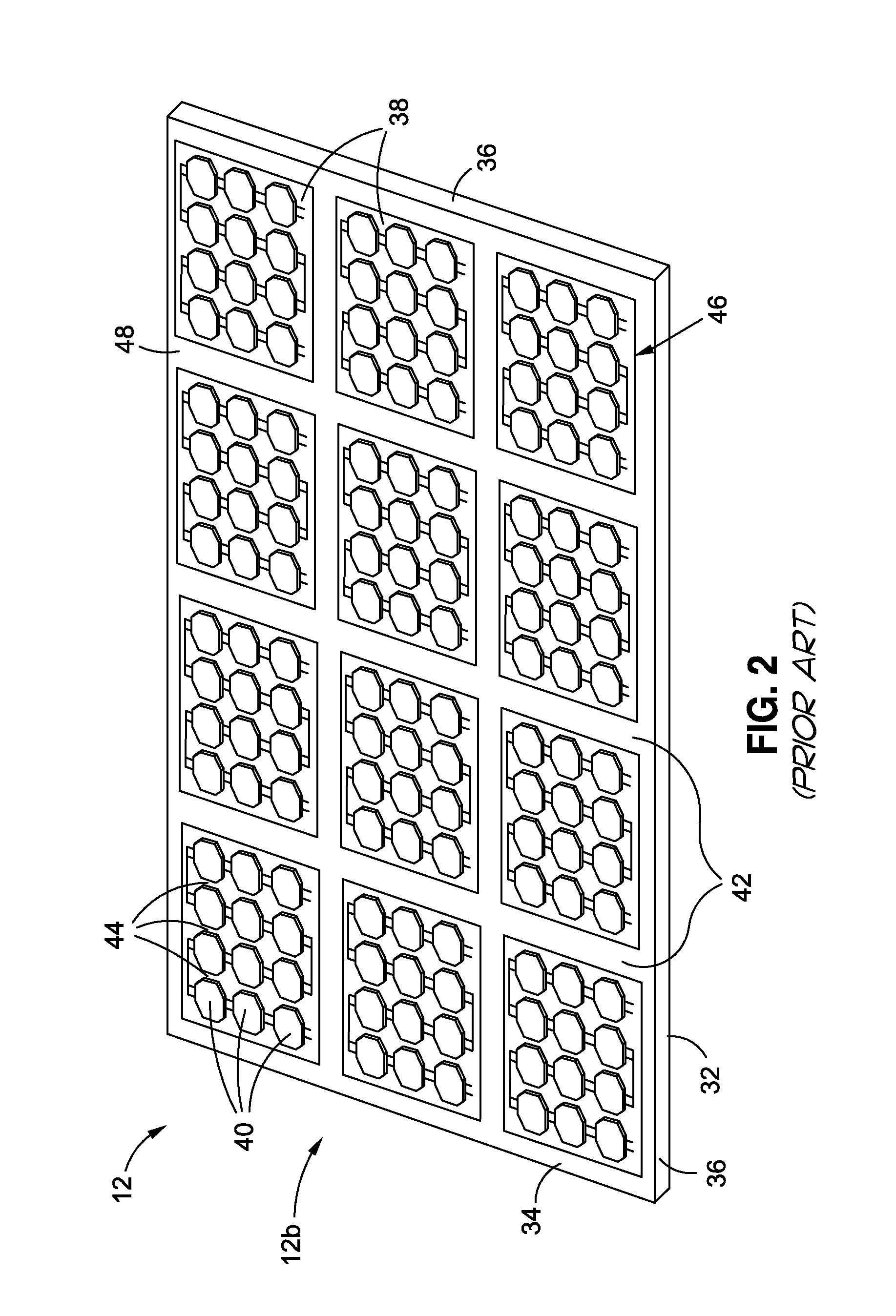
[0051]Now referring to the Figures, FIG. 1 is an illustration of a perspective view of an aircraft 10 which may incorporate one or more advantageous embodiments of a strain isolation layer assembly 50, 50a-50h, 50j (see FIGS. 4A-13C) of the disclosure. As shown in FIG. 1, the aircraft 10 is preferably solar powered and comprises one or more rigid solar layers 12, such as in the form of solar panels 12a. As further shown in FIG. 1, the aircraft 10 further comprises fuselages 14, tails 16, control system hou...


PUM


Abstract

In an embodiment of the disclosure, there is provided a strain isolation layer assembly. The assembly has a rigid solar layer; a strain isolation layer having a discontinuous configuration, a vertical rigidity, and a horizontal shear flexibility; and an underlying substrate layer. The strain isolation layer is coupled between the rigid solar layer and the underlying substrate layer to form a strain isolation layer assembly, such that the strain isolation layer isolates the rigid solar layer to reduce one or more strains induced on the rigid solar layer.

Description

REFERENCE TO GOVERNMENT CONTRACT[0001]This invention was made with Government support under Agreement No. HR0011-10-9-0010 awarded by Defense Advanced Research Projects Agency (DARPA). The government has certain rights in this invention.BACKGROUND[0002]1) Field of the Disclosure[0003]The disclosure relates generally to solar layers and solar panels mounted on structures, and more particularly, to assemblies and methods for improved mounting of such solar layers and solar panels on structures.[0004]2) Description of Related Art[0005]Solar technologies are increasingly being used to harvest solar energy and to power various vehicles and devices. For example, solar layers and panels, such as individual photovoltaic solar cells, or solar panel arrays comprised of photovoltaic solar cells, may be mounted to structures, such as transport vehicles and terrestrial and space-based structures, to harvest and convert solar energy into useful outputs such as electrical energy.[0006]Solar powere...

Claims


Application Information

Patent Timeline
IPC IPC(8): H01L31/048H01L31/18
CPCB64D2211/00Y02E10/50H02S10/40H01L31/0422B64C2201/042H02S20/00B64C2201/021Y02B10/20H01L31/042Y02T50/50B64U10/25B64U50/19B64U50/34B64D27/353
Inventor GRIP, ROBERT ERIKRAWDON, BLAINE KNIGHTCROOKS, TAB HUNTERSTOLA, MICHAEL F.
Owner THE BOEING CO
Learn More