
Method for sequentially measuring impedance, measurement device, and fuel cell system

Active Publication Date: 2013-04-25
HONDA MOTOR CO LTD
View PDF4 Cites 18 Cited by
  • Summary
  • Abstract
  • Description
  • Claims
  • Application Information

AI Technical Summary

Benefits of technology

The present invention aims to solve the problem of accurately measuring the impedance of a fuel cell by providing a sequential impedance measurement device, method, and fuel cell system. The device can precisely measure the impedance of a fuel cell using a sequential approach, allowing for more accurate analysis and optimization of fuel cell performance.

Problems solved by technology

Unfortunately, the FRA methods disclosed in Patent Literatures 1 to 3 are methods including inputting a sinusoidal wave at a predetermined frequency to perform a measurement.
Thus, it is only possible to determine impedance at the predetermined frequency.
Accordingly, it is difficult to perform real-time analysis of a rapid phenomenon whose effect occurs in a low-frequency range.
In addition, signals with different frequencies cannot be simultaneously applied.
For example, it is impossible to simultaneously determine and analyze a concentration overvoltage that occurs during the above flooding at the time of membrane resistance measurement.
Also, a superimposing device which applies an accurate sinusoidal wave is costly.
This frequently causes the situation that the measurement cannot be performed at any given timing.

Method used


Image

  • Method for sequentially measuring impedance, measurement device, and fuel cell system
  • Method for sequentially measuring impedance, measurement device, and fuel cell system
  • Method for sequentially measuring impedance, measurement device, and fuel cell system

Examples


first embodiment

Sequential Impedance Measurement Device

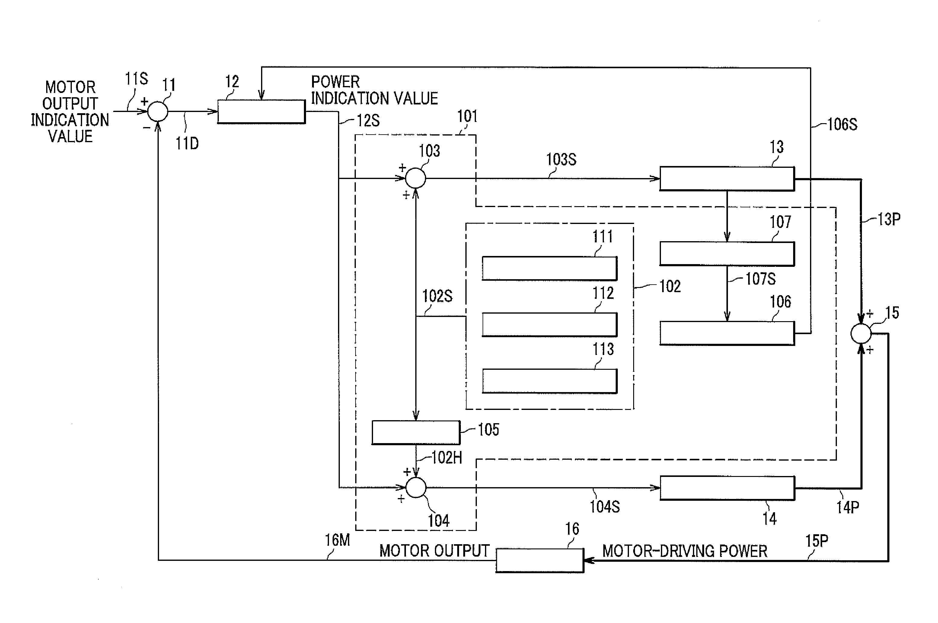
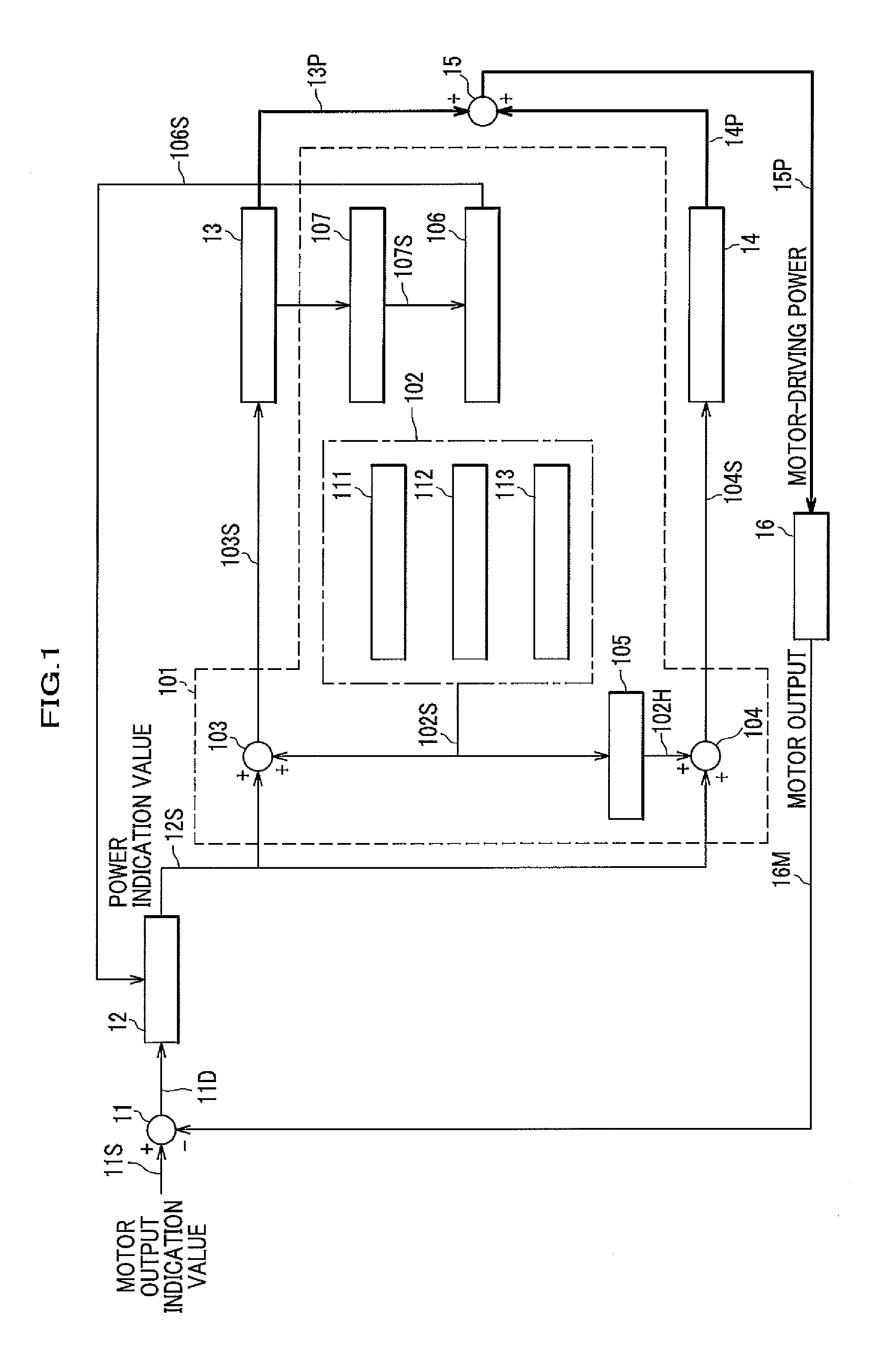
[0048]FIG. 1 illustrates the first configuration in which a fuel cell vehicle includes a sequential impedance measurement device according to the first embodiment of the present invention.

[0049]In FIG. 1, a sequential impedance measurement device 101 according to the first embodiment of the present invention includes an FFT impedance-measuring-signal-generating unit 102, a first signal-adding unit 103, and a second signal-adding unit 104, a signal-inverting unit 105, an impedance calculator (designated as “IMP CALCULATOR” in FIG. 1) 106, and a current and voltage measuring unit 107.

[0050]In addition, the FFT impedance-measuring-signal generating unit 102 includes an M-sequence-signal-generating section 111, a superimposed-signal-generating section 112, and a signal-processing section 113.

[0051]A fuel cell vehicle (not shown) includes a fuel cell 13 which is a power source for driving a vehicle, a battery 14 which serves as an aid for the fuel c...

second embodiment

Sequential Impedance Measurement Device

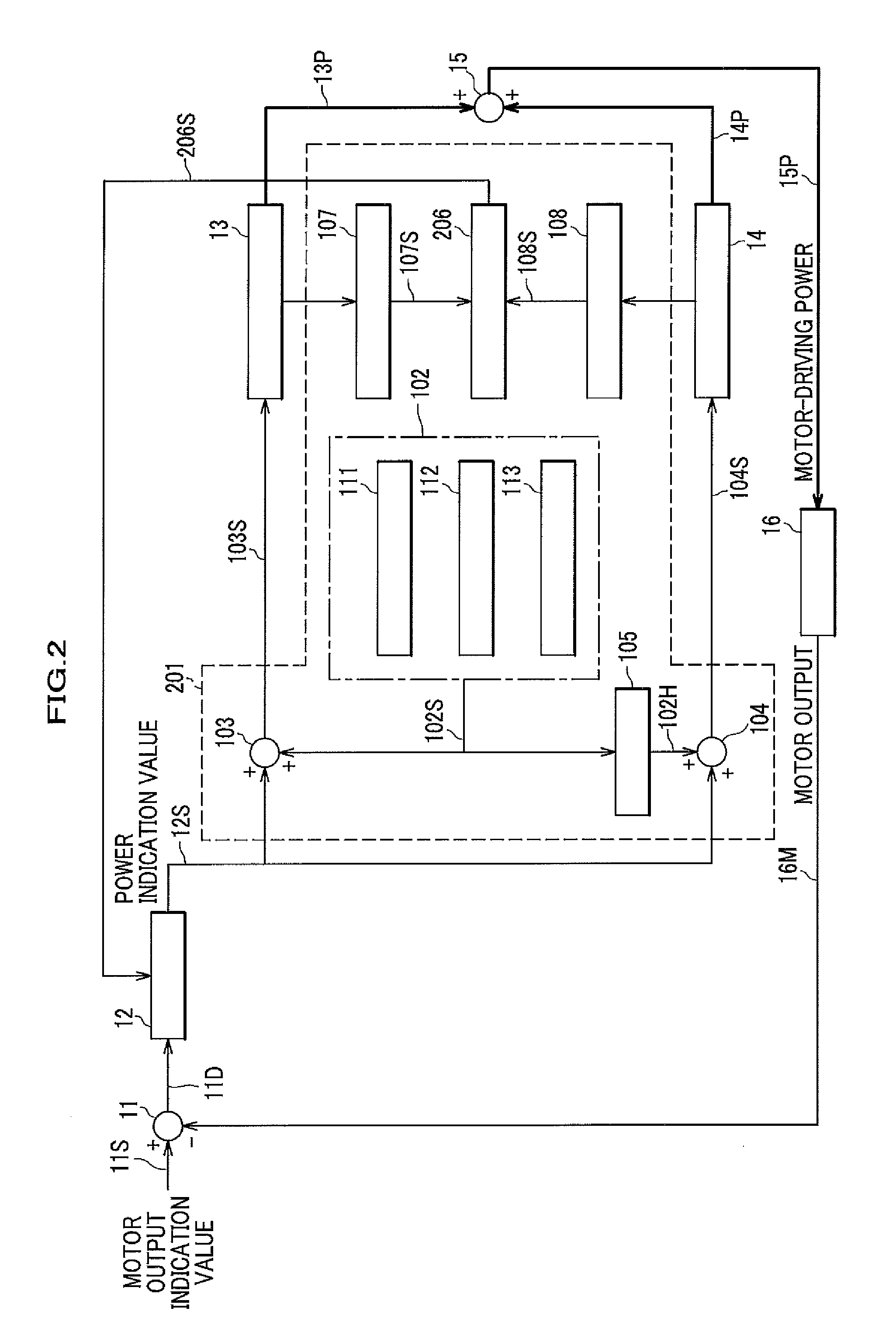
[0073]FIG. 2 illustrates the second configuration in which a fuel cell vehicle includes a sequential impedance measurement device according to the second embodiment of the present invention.

[0074]FIG. 2 differs from FIG. 1 in that a sequential impedance measurement device 201 further includes a second current and voltage measuring unit 108. The unit determines current and voltage values of the battery 14. Then, the unit sends to an impedance calculator 206 the values as a measured current and voltage value 108S.

[0075]The impedance calculator 206 performs not only an impedance calculation of the fuel cell 13 but also that of the battery 14. After that, the impedance calculator transmits an impedance-value-indicating signal 206S regarding the fuel cell 13 and the battery 14 to the control processor 12. Finally, the control processor 12 refers to the impedance values of the fuel cell 13 and battery 14 to control the power indication value 12S.

[007...

third embodiment

Method for Sequentially Measuring Impedance

[0089]The following below describes another embodiment, a method for sequentially measuring impedance according to the third embodiment of the present invention.

(Flow of Impedance Measurement Processed by FFT Processing)

[0090]The following illustrates how to process an impedance measurement by FFT processing in a method for sequentially measuring impedance.

[0091]FIG. 4 is a flow chart illustrating how to process an impedance measurement by FFT processing. The flow chart describes each step one by one.

401>>

[0092]First, an M-sequence signal is determined. The M-sequence has various patterns such as a short one and a long one. Depending on a calculation time (calculation speed) and precision conditions involving a calculation, the M-sequence signal is selected and determined.

[0093]Note that in FIG. 3, the M-sequence-signal-generating section 311 of the FFT impedance-measuring-signal-generating unit 302 determines the M-sequence signal.

[0094]Of...


PUM


Abstract

Provided are a sequential impedance measurement device and a method for sequentially measuring impedance. While applying a signal having a power output fluctuation similar to that of normal operation, it is possible to carry out a quick measurement with relatively high precision and in a broad frequency range. Also, the device and the method can simultaneously determine phenomena which occur in different frequency ranges. Disclosed is a sequential impedance measurement device in which impedance of a fuel cell is sequentially measured in a control system, the control system controlling the fuel cell by using a power indication value of a control processor, the device including: an M-sequence-signal-generating section; a superimposed-signal-generating section; a signal-processing section; a signal-adding unit; a current and voltage measuring unit; and an impedance calculator, wherein a method for controlling the fuel cell by the control processor is modified according to a calculation result of the impedance calculator.

Description

BACKGROUND OF THE INVENTION[0001]1. Field of the Invention[0002]The present invention relates to methods for sequentially measuring impedance of a fuel cell, measurement devices, and fuel cell systems.[0003]2. Description of the Related Art[0004]Recently, fuel cell electric vehicles (FCEV) have drawn attention to promote environmental programs and to decrease fossil fuel consumption.[0005]The fuel cell electric vehicle (hereinafter, referred to as a “vehicle” or “fuel cell vehicle”) includes a fuel cell whose impedance characteristic is a critical element for vehicle driving performance and should be sequentially determined.[0006]The fuel cell, however, has different impedance values because of different power generation conditions (e.g., a temperature, pressure, relative humidity) and / or driving conditions (e.g., a stoppage, start, high speed driving, high altitude driving, hill climbing). In addition, even under constant power generation conditions and / or driving conditions, the i...

Claims


Application Information

Patent Timeline
IPC IPC(8): G05F1/66
CPCG05F1/66Y02E60/50G01R31/3662G01R31/3651H01M2250/20H01M8/04552H01M8/04582H01M8/04641Y02T90/32G01R31/367G01R31/389Y02T90/40
Inventor EGAMI, MASAHIROYOSHIDA, HIROMICHIWAKE, CHIHIRO
Owner HONDA MOTOR CO LTD
Learn More