
Microdisplay-based head-up display system

a display system and micro-display technology, applied in the field of single or multi-color micro-display-based hud systems, can solve the problems of difficult to compensate for the aberration produced by the combiner, the combiner then unfortunately exhibits flare or multiple imaging, and the appearance of flare or undesired brightness around the object is perceived

Active Publication Date: 2013-04-25
EPIC OPTIX
View PDF13 Cites 63 Cited by
  • Summary
  • Abstract
  • Description
  • Claims
  • Application Information

AI Technical Summary

Benefits of technology

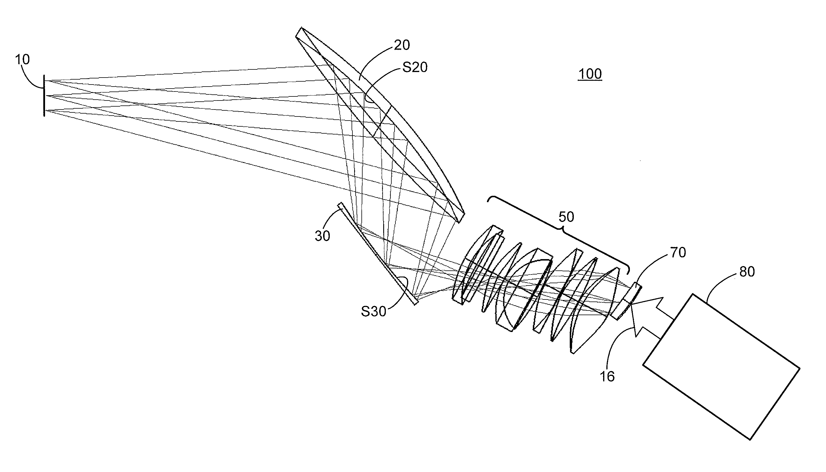
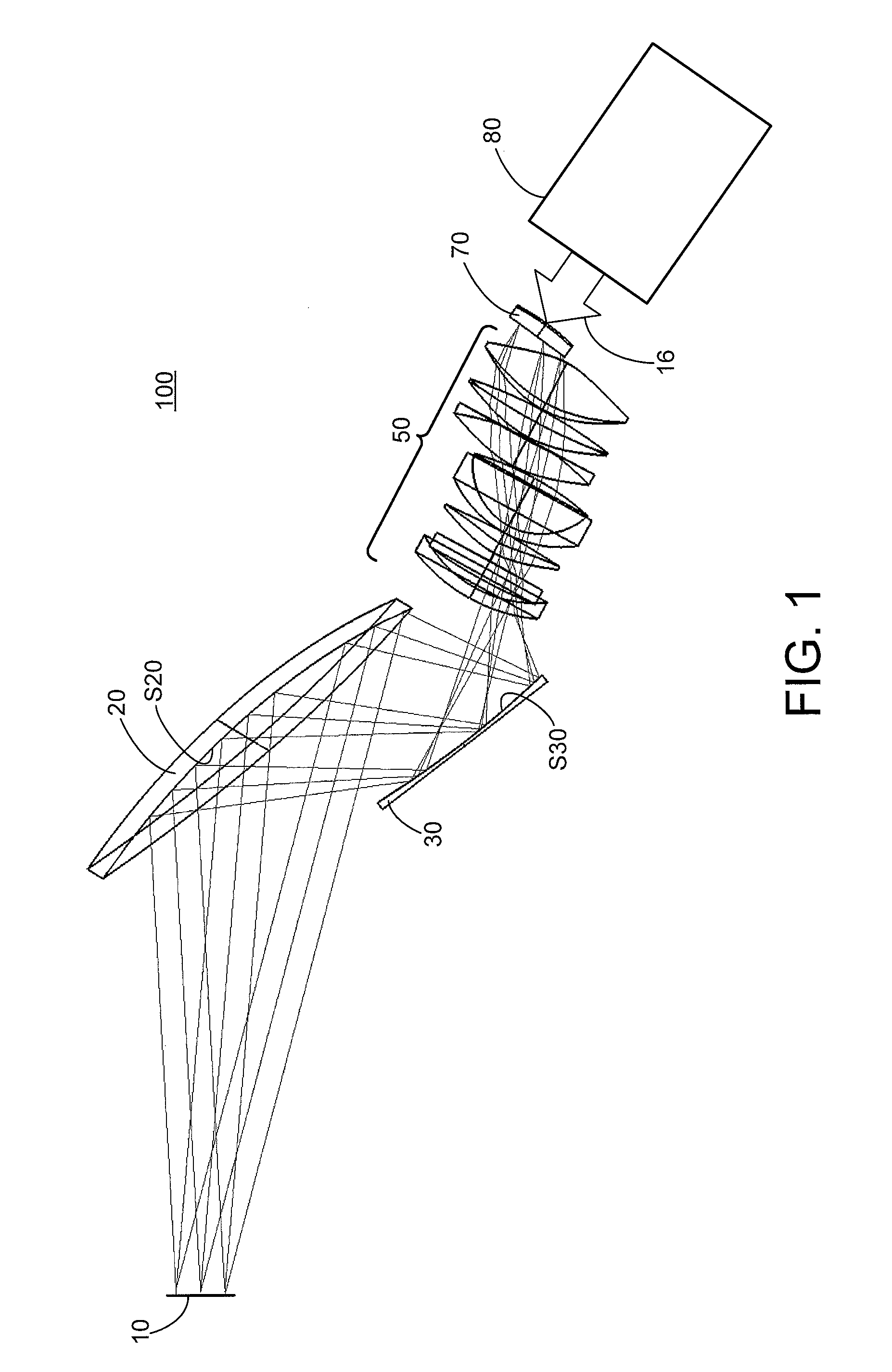
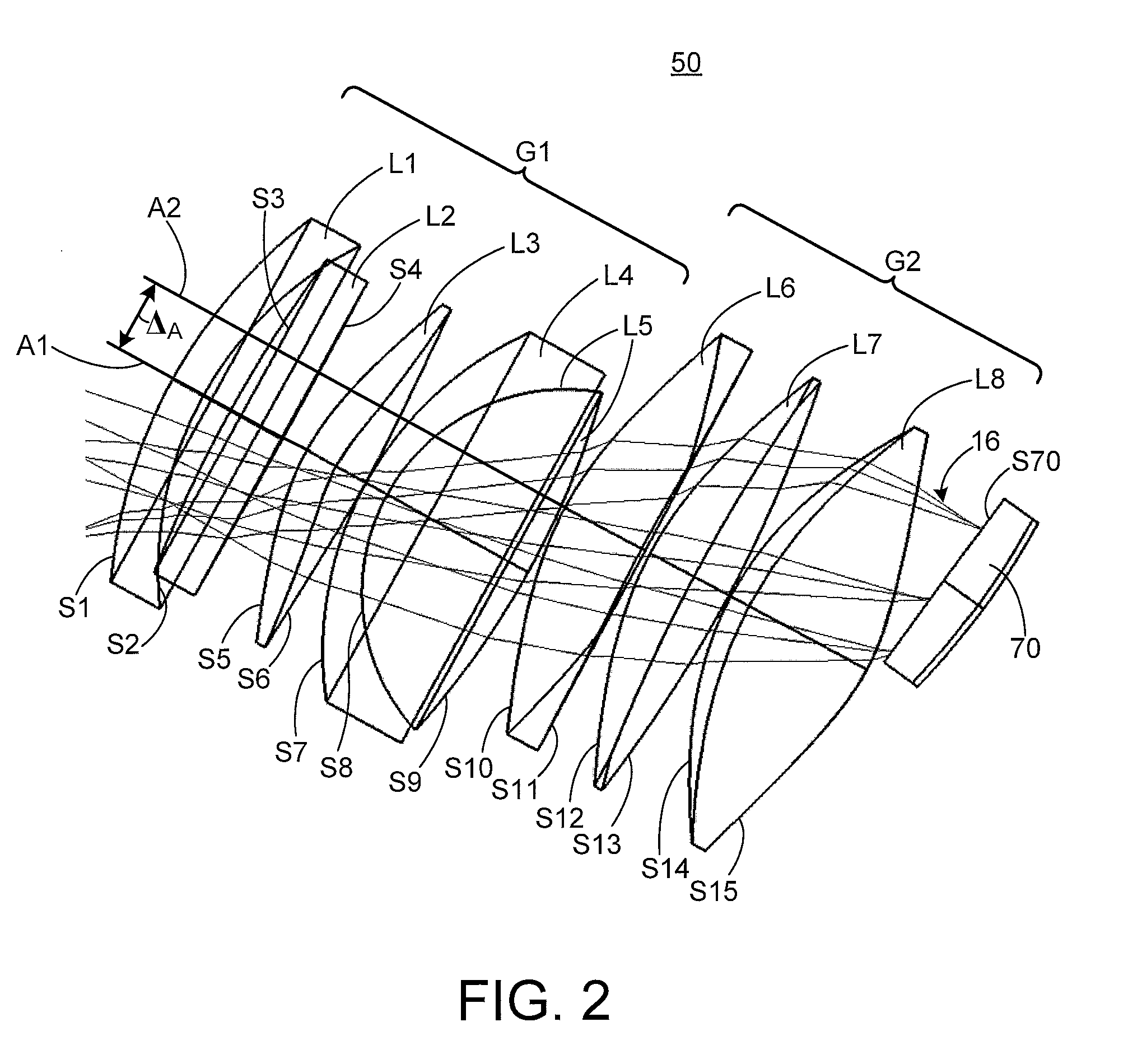
The present invention is about a HUD system that uses a diffuser and a microdisplay-based projection system to create a virtual image in the far field. A relay optical system is used to receive and partially reflect the diffused image to an observer of the display system. The HUD system also includes an anamorphic aspheric semi-reflective surface of a combiner that partially reflects and transmits light to the observer, along with an anamorphic aspheric mirror to correct the aberrations caused by the combiner. The technical effects of this invention include a more comfortable and realistic heads-up display for the observer, improved image quality, and reduced system complexity and cost.

Problems solved by technology

However, at large off-axis angles in a wide field-of-view system, it is quite difficult to compensate for the aberrations produced by the combiner without also providing aberration correction optical features in the combiner itself.
And, even though aberration correction optical power may be built into the combiner, the combiner then unfortunately exhibits flare or multiple imaging.
Thus, if a bright outside source is viewed through the combiner, such as runway lights at night, the appearance of flare or an undesired brightness around the object is perceived.
However, holograms, traditionally recorded, for example, in dichromated gelatin, are very expensive, have short lifetimes, and are sensitive to environmental conditions / changes such as vibrations, pressure, humidity, and temperature.
The optical functionality of holographic mirrors is subject to being dependent on a limited (narrower) spectrum of light and / or the size of the light source.
For example, a broader spectrum of light results in a decrease in image quality.
Moreover, a larger light source (which in the case of a HUD system is required to fill the field-of-view / eye-motion box) results in a decrease in image quality.
Holographic combiners are also notoriously known to be significantly limited in optical power.
Moreover, there is usually very limited space available in an aircraft cabin for a HUD system.
However, tilting of individual optical elements creates fundamental difficulties with achieving required accuracy for system alignment.
Accordingly, the above conventional HUD systems all suffer from various drawbacks such as excessive weight and size (i.e. associated with CRT-based HUD systems), excessive aberrations, optical element alignment and machining / molding complexities in achieving required accuracy, excessive manufacturing costs, sensitivity to environmental conditions / changes, etc.

Method used


Image

  • Microdisplay-based head-up display system
  • Microdisplay-based head-up display system
  • Microdisplay-based head-up display system

Examples


Embodiment Construction

[0019]It is to be understood that the figures and descriptions of the present invention may have been simplified to illustrate elements that are relevant for a clear understanding of the present invention, while eliminating, for purposes of clarity, other elements found in a typical HUD system. Those of ordinary skill in the art will recognize that other elements may be desirable and / or required in order to implement the present invention. However, because such elements are well known in the art, and because they do not facilitate a better understanding of the present invention, a discussion of such elements is not provided herein. It is also to be understood that the drawings included herewith only provide diagrammatic representations of the presently preferred structures of the present invention and that structures falling within the scope of the present invention may include structures different than those shown in the drawings. Reference will now be made to the drawings wherein ...


PUM


Abstract

A head-up display (HUD) system is provided. The HUD system comprises a microdisplay-based projection system, a diffuser, a relay optical system, and a combiner. The microdisplay-based HUD system includes aberration correction capabilities and may easily and effectively replace a CRT-based HUD system in aircrafts while providing light-weight, multi-color, superior imaging capabilities with a large field-of-view.

Description

FIELD OF THE INVENTION[0001]The present invention relates generally to the field of head-up display (HUD) systems, and, more specifically, to single or multi-color microdisplay-based HUD systems including aberration correction capabilities and having a large field-of-view.BACKGROUND OF THE INVENTION[0002]HUD systems have been well known for many years, and are used or are being considered for use in many applications such as aircraft, automobiles, medical, scientific data visualization, boats, large farm equipment, and heavy-duty construction equipment. Existing HUD systems create an image that is projected into the field-of-view of a user so that the user can glance at the projected image whenever the information contained in the image is needed. In aircraft applications, the pilot visualizes the HUD information in the field-of-view along with the outside world (i.e. real-world) in the flight path ahead and real objects on or near the flight path. More particularly, a HUD system fo...

Claims


Application Information

Patent Timeline
IPC IPC(8): G02B27/01G02B17/08
CPCG02B17/08G02B5/02G02B5/10G02B2027/011G02B2027/0118G02B27/0101
Inventor MAGARILL, SIMONKIM, DONGHA
Owner EPIC OPTIX
Learn More