Image processing device, imaging capturing device, and method for processing image
a technology of image processing and imaging capturing, which is applied in the field of image processing devices, image processing methods, and image capturing devices, can solve the problems of increased fatigue and inability to stereoscopic fusion, and achieve the effect of visual discomfor
- Summary
- Abstract
- Description
- Claims
- Application Information
AI Technical Summary
Benefits of technology
Problems solved by technology
Method used
Image


Examples
first embodiment
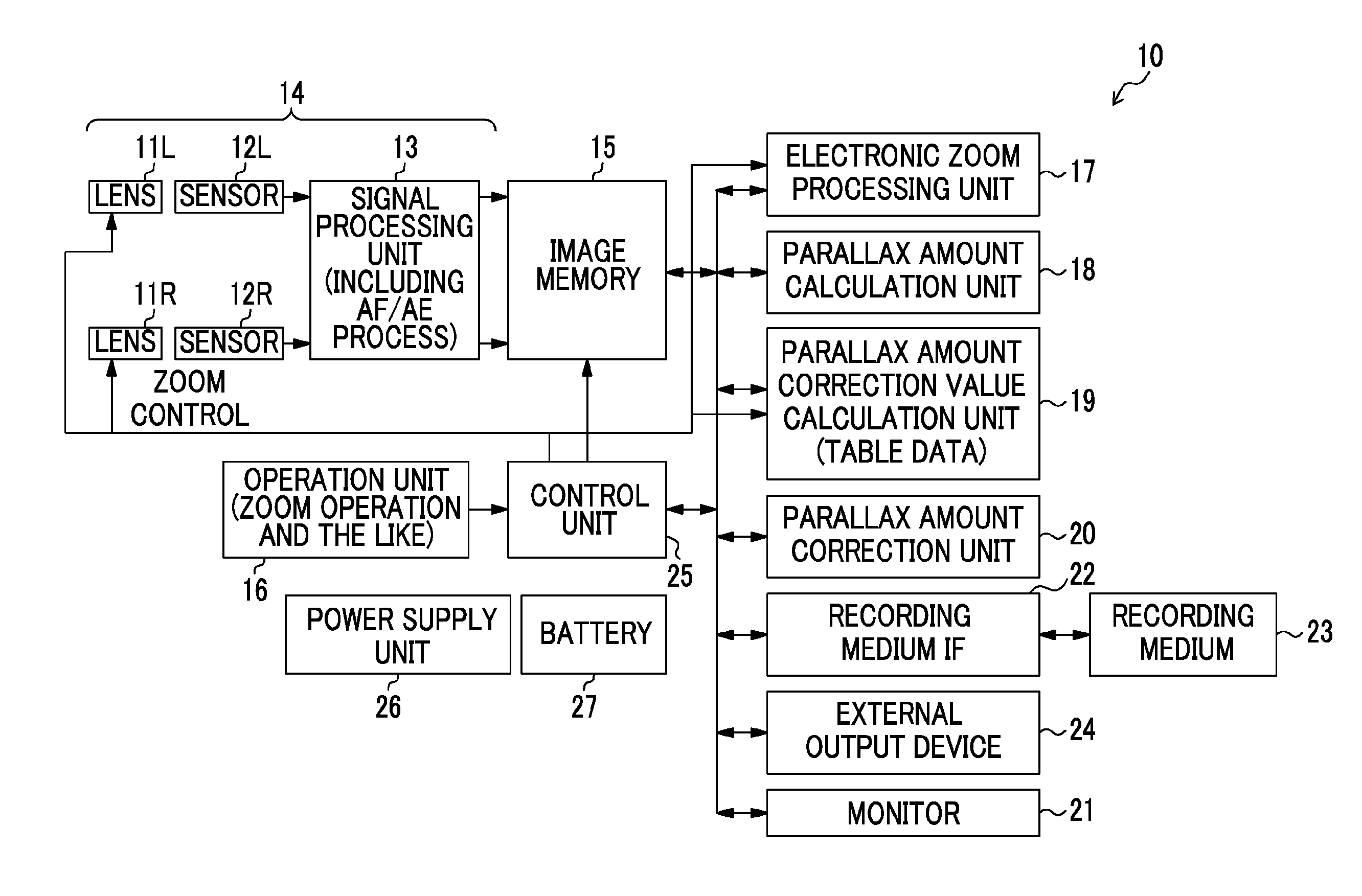
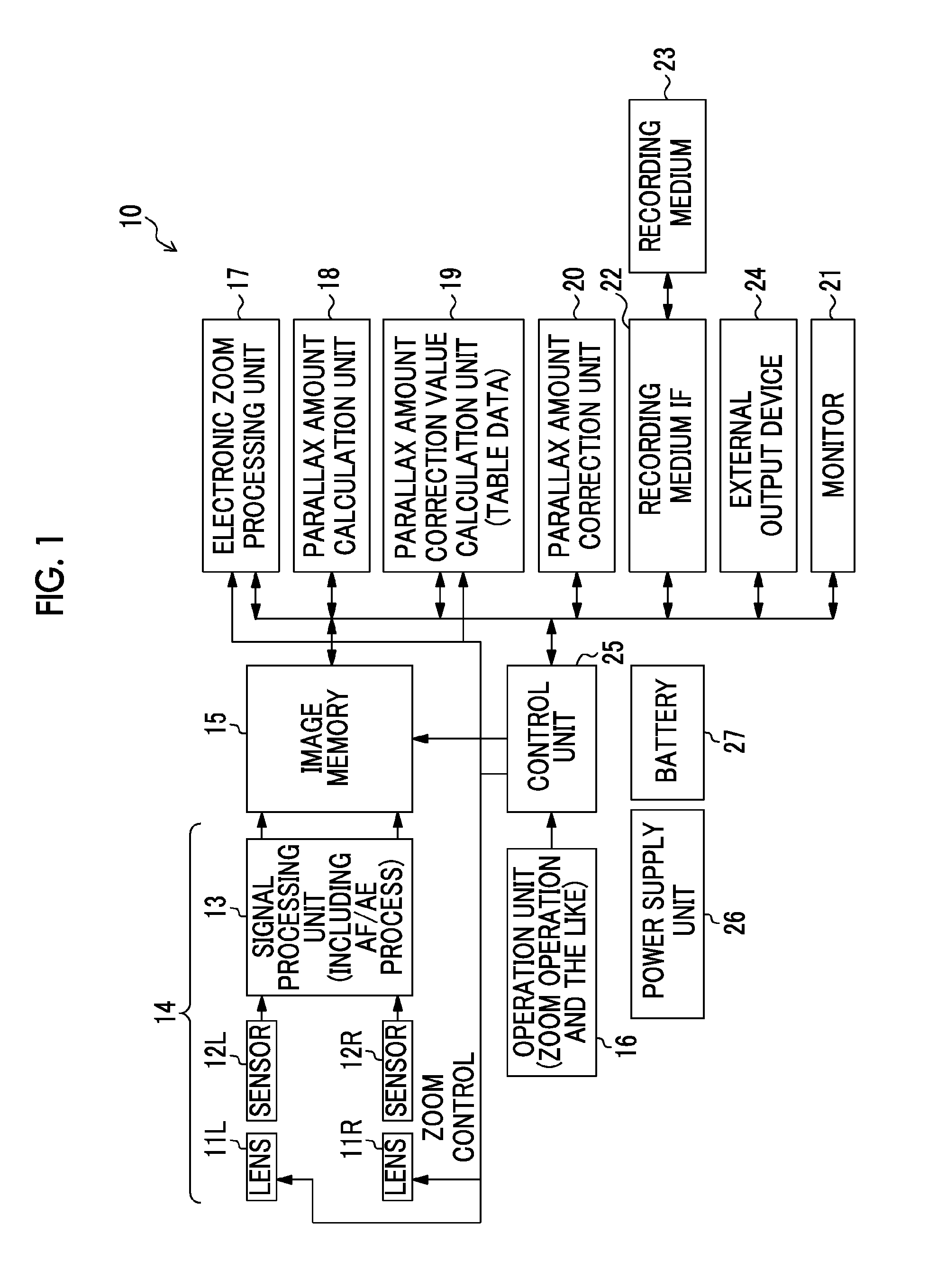
[0053]FIG. 1 is a block diagram illustrating a configuration example of the image capturing device related to the present invention.
[0054]An image capturing device 10 includes imaging lenses 11L and 11R, imaging sensors 12L and 12R, a signal processing unit 13, an image memory 15, an operation unit 16, an electronic zoom processing unit 17, a parallax amount calculation unit 18, a parallax amount correction value calculation unit 19, a parallax amount correction unit 20, a monitor 21, a recording medium interface 22, a recording medium 23, an external output device 24, a control unit 25, a power supply unit 26, and a battery 27.
[0055]The imaging lenses 11L and 11R include an optical system which forms a subject image on light receiving surfaces of the imaging sensors 12L and 12R. The imaging lenses 11L and 11R in this example include a focus lens, a zoom lens, and a diaphragm device.
[0056]The imaging sensors 12L and 12R capture the subject image formed on the imaging lenses 11L and ...
second embodiment
[0118]Next, the second embodiment will be described. In the second embodiment, a zooming effect is emphasized, and parallax excess or parallax divergence is also prevented, by increasing a variation amount of a parallax amount relative to a variation amount of a zoom value.
[0119]FIG. 13 illustrates a correspondence relationship (parallax distribution) between a zoom value and a parallax amount in a viewpoint image after a parallax is corrected by the parallax amount correction unit 20 according to the second embodiment.
[0120]In order to emphasize zooming, preferably, a variation amount of the parallax amount relative to a variation amount of the zoom value is increased by further increasing the slope of each of the line between Ptf and Pwf and the line between Ptn and Pwn. In other words, a movement amount of a subject in the depth direction relative to a variation of a zoom value in stereoscopic images increases, and thereby a zooming effect can be emphasized.
[0121]In that case, as...
third embodiment
[0133]There are cases where a subject distance range is narrow in practical photographing. For example, in photographing indoors, there is no infinite subject, and, in photographing outdoors, even a point-blank range is a more distant range than MOD (shortest focusing distance). In that case, a distance of parallax amounts after being corrected lies, for example, in a range between the dotted line 31 and the dotted line 32 of FIG. 17. In this case, since there is a margin to the limit values (Ptn and Pwf) from the maximum value Pa and the minimum value Pb in a practical parallax distribution, the margin can be assigned for emphasis of a zooming effect.
[0134]Specifically, shift amounts 51 and S2 of parallax correction may be adjusted such that the maximum value Pa becomes the upper limit value Ptn, and the minimum value Pb becomes the lower limit value Pwf. As a result, after parallax correction is performed, the parallax distribution is changed from the range between the dotted line...
PUM
 Abstract
Description
Claims
Application Information
 - R&D
- Intellectual Property
- Life Sciences
- Materials
- Tech Scout
- Unparalleled Data Quality
- Higher Quality Content
- 60% Fewer Hallucinations
Browse by: Latest US Patents, China's latest patents, Technical Efficacy Thesaurus, Application Domain, Technology Topic, Popular Technical Reports.
© 2025 PatSnap. All rights reserved.Legal|Privacy policy|Modern Slavery Act Transparency Statement|Sitemap|About US| Contact US: help@patsnap.com