
Shielding apparatus and wireless power transmission apparatus

a wireless power transmission and shielding technology, applied in the direction of magnetic bodies, cores/yokes, inductances, etc., can solve the problems of affecting the health of the human body, erroneous etc., to reduce the radiation quantity of electromagnetic field leaked to the outside in the wireless power transmission process, inhibit the operation of another device, and minimize the effect of harmful influen

Active Publication Date: 2013-04-25
SCRAMOGE TECH LTD
View PDF9 Cites 13 Cited by
  • Summary
  • Abstract
  • Description
  • Claims
  • Application Information

AI Technical Summary

Benefits of technology

The patent describes a shielding apparatus that can improve the efficiency of wireless power transmission between a wireless power transmission apparatus and a wireless power reception apparatus. The shielding apparatus can prevent other devices from operating incorrectly and minimize the harmful effects on the human body caused by leaked magnetic fields. Additionally, the apparatus can maximize power efficiency by changing the transmission path of the magnetic field through the shielding apparatus.

Problems solved by technology

However, according to the energy transfer method employing resonance, another device may erroneously operate due to an electromagnetic wave generated from the transmitter.
The electromagnetic wave, which is exposed to a human body, may exert a harmful influence on the health of the human body.

Method used


Image

  • Shielding apparatus and wireless power transmission apparatus
  • Shielding apparatus and wireless power transmission apparatus
  • Shielding apparatus and wireless power transmission apparatus

Examples


Embodiment Construction

[0022]Terms and words used in the specification and the claims shall not be interpreted as commonly-used dictionary meanings, but shall be interpreted as to be relevant to the technical scope of the invention based on the fact that the inventor may property define the concept of the terms to explain the invention in best ways.

[0023]Therefore, the embodiments and the configurations depicted in the drawings are illustrative purposes only and do not represent all technical scopes of the embodiments, so it should be understood that various equivalents and modifications may exist at the time of filing this application.

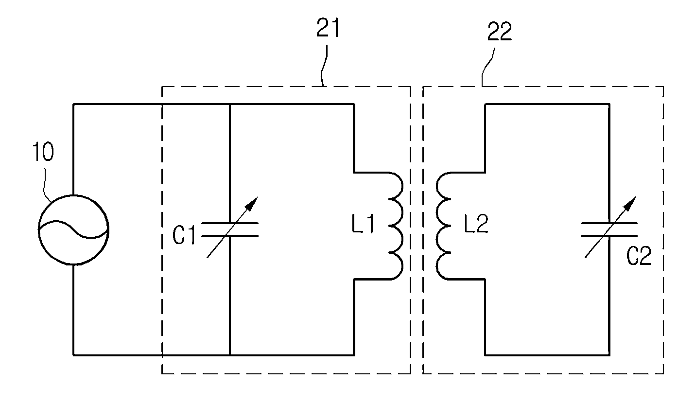
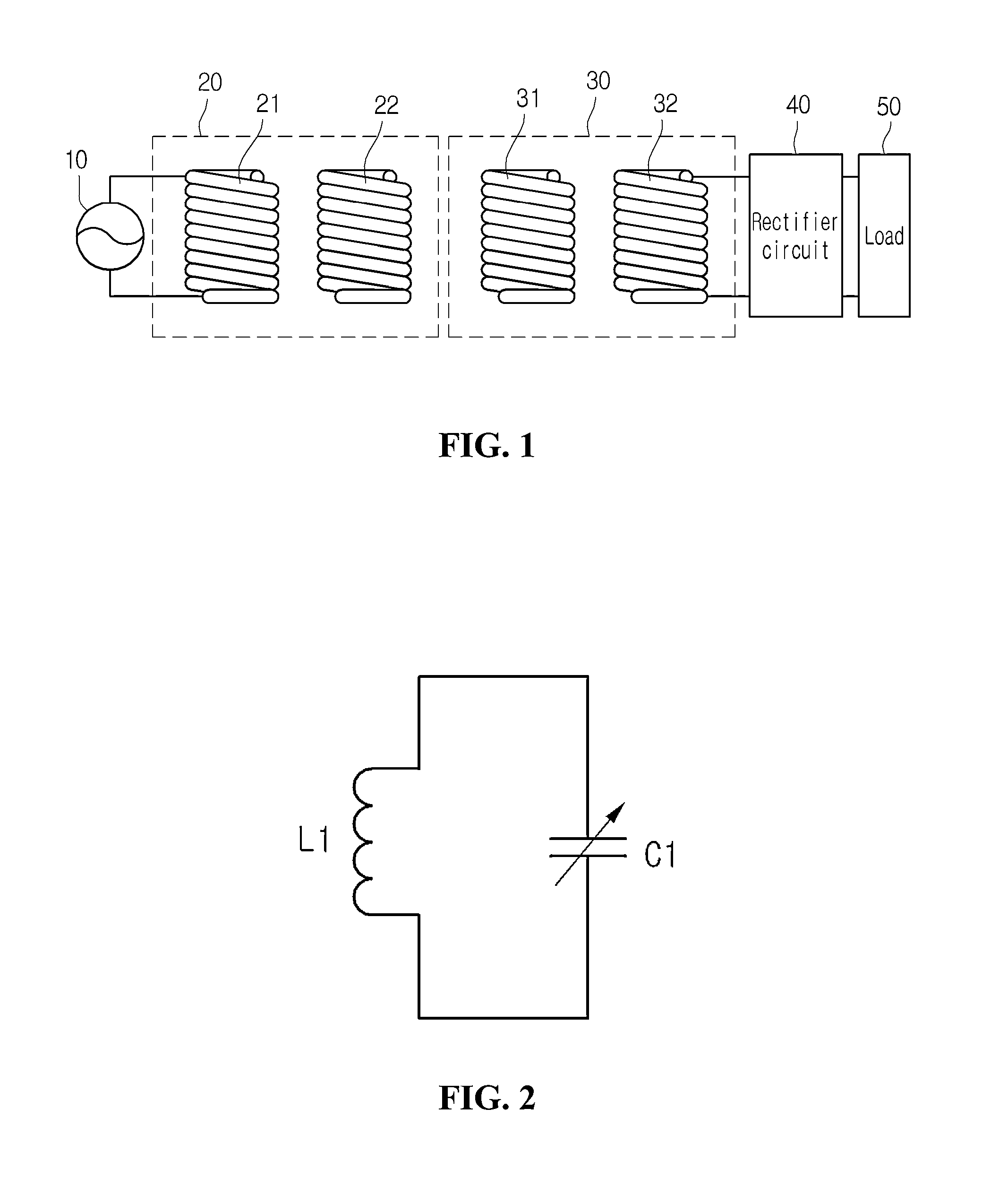
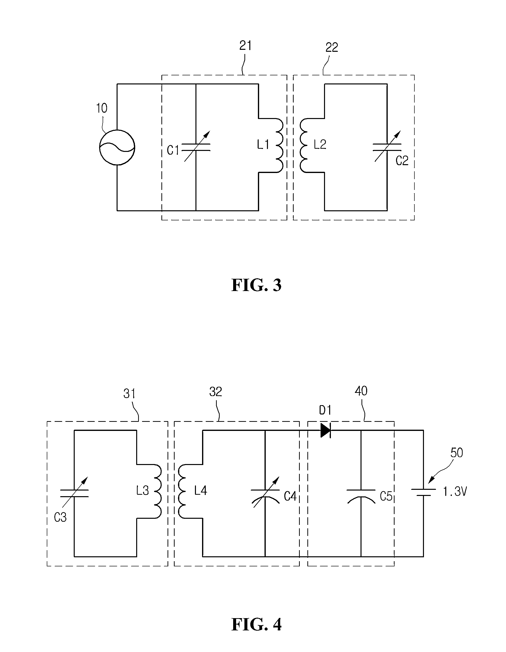
[0024]FIG. 1 is a view showing a wireless power transmission system according to the embodiment of the disclosure.

[0025]The power generated from a power source 10 is provided to a power transmitting unit 20, such that the power transmitting unit 20 transmits the power using resonance to a power receiving unit 30, which is resonant with the power transmitting unit 20 and has...


PUM

PropertyMeasurementUnit
magnetic fieldaaaaaaaaaa
permeabilityaaaaaaaaaa
magneticaaaaaaaaaa

Abstract

Disclosed are a shielding apparatus and a wireless power transmission apparatus. The shielding apparatus included in a wireless power transmission apparatus for transmitting power to a wireless power reception apparatus in wireless includes a first shielding unit changing a transmission path of a portion of a magnetic field generated from a transmission coil of the wireless power transmission apparatus, and a second shielding unit shielding the portion of the magnetic field which has passed through the first shielding unit. The second shielding unit is placed on the first shielding unit. A real component value of permeability of the first shielding unit is greater than an imaginary component value of the permeability of the first shielding unit, and an imaginary component value of permeability of the second shielding unit is greater than a real component value of the permeability of the second shielding unit.

Description

CROSS-REFERENCE TO RELATED APPLICATION[0001]This application claims the benefit under 35 U.S.C. §119 of Korean Patent Application No. 10-2011-0108960, filed Oct. 24, 2011, which is hereby incorporated by reference in its entirety.BACKGROUND[0002]The disclosure relates to a shielding apparatus and a wireless power transmission apparatus. The disclosure relates to a wireless power transmission technology capable of improving power transmission efficiency and minimizing the quantity of a magnetic field to be leaked to the outside.[0003]A wireless power transmission or a wireless energy transfer refers to a technology of wirelessly transferring electric energy to desired devices. In the 1800's, an electric motor or a transformer employing the principle of electromagnetic induction has been extensively used and then a method for transmitting electrical energy by irradiating electromagnetic waves, such as radio waves or lasers, has been suggested. Actually, electrical toothbrushes or elec...

Claims


Application Information

Patent Timeline
Patent Type & Authority Applications(United States)
IPC IPC(8): H05K9/00H01F38/14H01F1/00H01F1/12H01F1/147
CPCH01F27/36H01F38/14H02J7/025H04B5/0081H02J5/005H04B5/0037H01F2003/106H01F27/361H01F27/366H02J50/12H02J50/70H04B5/26H04B5/79H02J50/005H02J50/80
Inventor AN, JEONG WOOK
Owner SCRAMOGE TECH LTD
Learn More