
Differential Driver, Circuits and Devices Including the Same, and Method(s) of Manufacturing the Same

a technology of differential drivers and drivers, applied in the field of optical data communication and optical network technology, can solve the problems of smoothing the rise and fall of waveforms, and achieve the effects of smooth input, less abrupt increase and decrease of amplitude, and high jitter and dispersion penalty

Active Publication Date: 2013-04-18
SOURCE PHOTONICS
View PDF2 Cites 9 Cited by
  • Summary
  • Abstract
  • Description
  • Claims
  • Application Information

AI Technical Summary

Benefits of technology

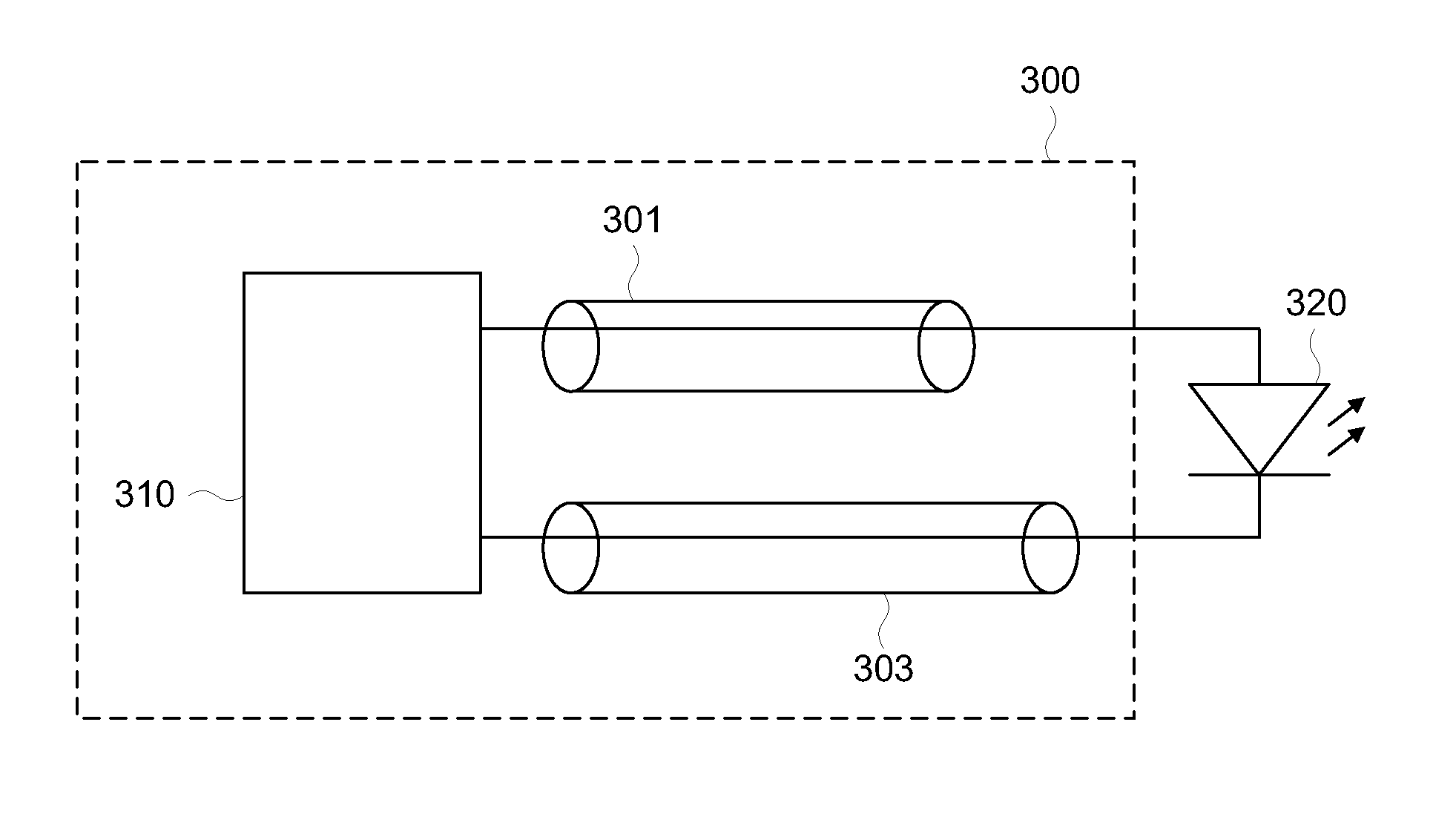
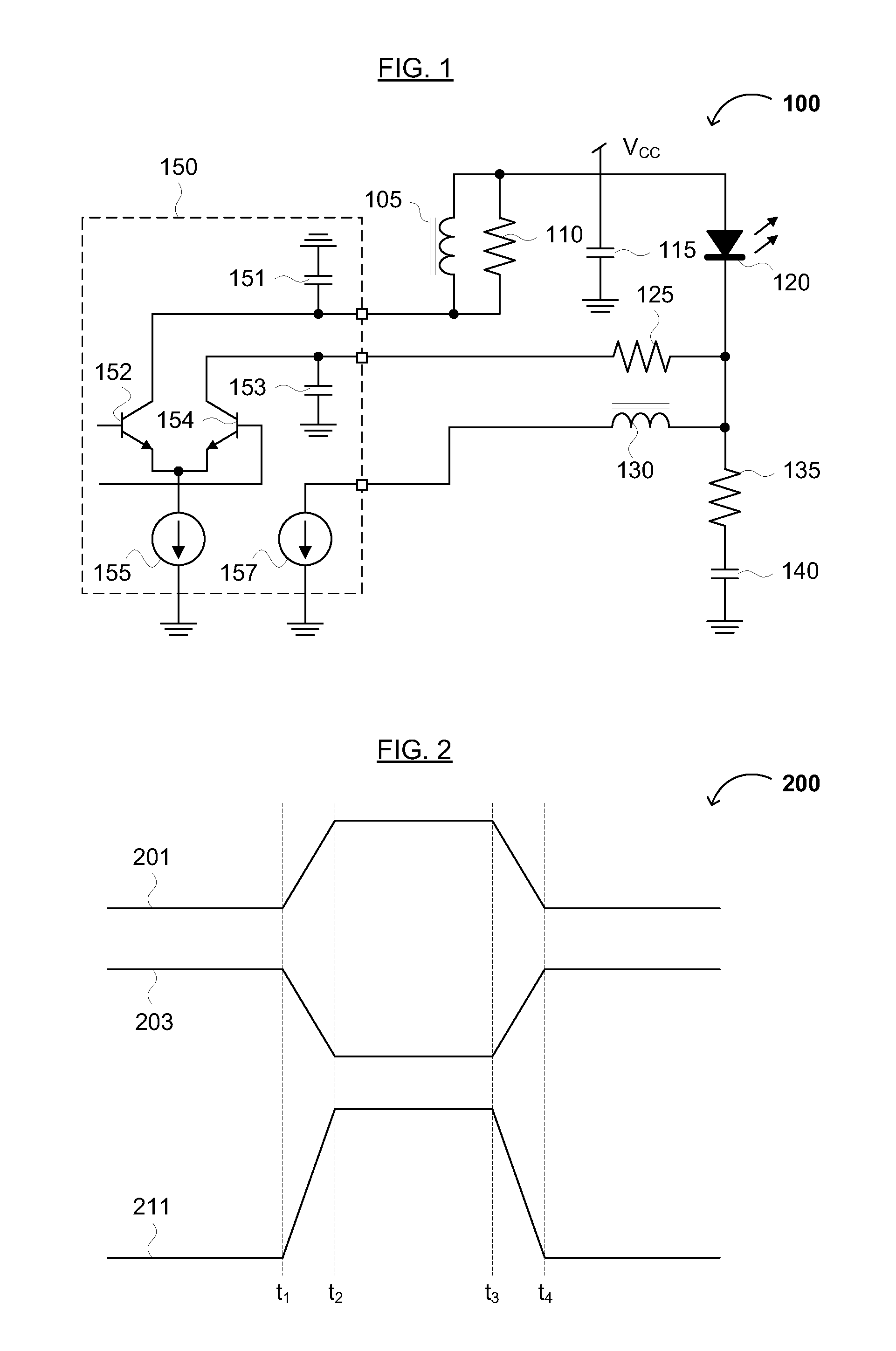
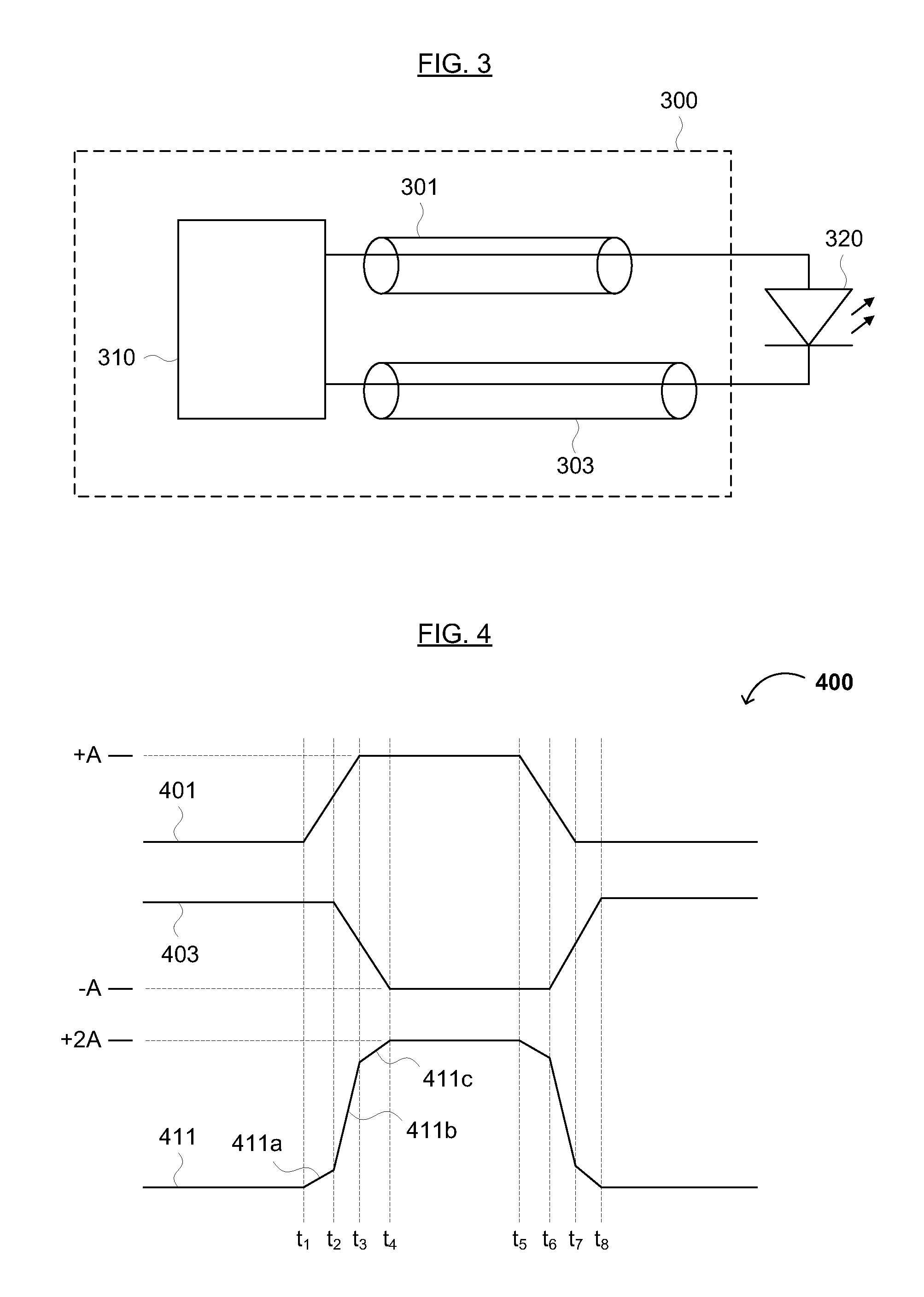
The present invention is about an optical output circuit that uses a differential driver and two transmission lines to smoothly transmit optical signals to a load. This results in a smoother waveform with low jitter, minimal chirps, and reduced dispersion penalty. The invention is useful for both DC-coupled and AC-coupled configurations, and can improve load matching. This technology solves the problems of high jitter and dispersion penalty associated with sharp, high-speed transitions in differential signals. The invention provides a better match between the waveform and the load, lower overshoot, and reduced dispersion penalty.

Problems solved by technology

That is, improving the waveform provided to the load through an unbalanced signal transmission makes the rise and fall of the waveform smoother.

Method used


Image

  • Differential Driver, Circuits and Devices Including the Same, and Method(s) of Manufacturing the Same
  • Differential Driver, Circuits and Devices Including the Same, and Method(s) of Manufacturing the Same
  • Differential Driver, Circuits and Devices Including the Same, and Method(s) of Manufacturing the Same

Examples


Embodiment Construction

[0017]Reference will now be made in detail to various embodiments of the invention, examples of which are illustrated in the accompanying drawing(s). In order to achieve the objectives, technical solutions and advantages of the present invention more clearly, further details of the invention are described below with regard to the Figure(s). While the invention will be described in conjunction with the following embodiments, it will be understood that the descriptions are not intended to limit the invention to these embodiments. On the contrary, the invention is intended to cover alternatives, modifications and equivalents that may be included within the spirit and scope of the invention as defined by the appended claims. Furthermore, in the following detailed description, numerous specific details are set forth in order to provide a thorough understanding of the present invention. However, it will be readily apparent to one skilled in the art that the present invention may be practi...


PUM

PropertyMeasurementUnit
Timeaaaaaaaaaa
Timeaaaaaaaaaa
Timeaaaaaaaaaa

Abstract

The present disclosure relates to a differential drive circuit. The differential drive circuit generally includes a differential driver, a first transmission line coupled to a first output node of the differential driver, and a second transmission line coupled to a second output node of the differential driver. A laser diode is coupled to the first and second transmission lines. The first and second transmission lines have different delays, lengths, or impedances. In some embodiments, the delay between the first transmission line and the second transmission line is 0.2-0.4 times a rise time or fall time of a signal on either transmission line.

Description

CROSS REFERENCE TO RELATED APPLICATION[0001]This application claims the benefit of Chinese Patent Application Nos. 201110309634.1 and 201110389727.X, filed on Oct. 13, 2011 and Nov. 30, 2011, respectively, and each of which is hereby incorporated by reference as if fully set forth herein.FIELD OF THE INVENTION[0002]The present invention generally relates to the field of optical data communications and optical network technology (e.g., laser communications). More specifically, embodiments of the present invention pertain to a differential drive circuit for a laser diode, an optical output circuit including the laser diode, devices and transceivers including the same, and method(s) of making the same. In some embodiments, the differential drive circuit and / or optical output circuit is for 1.25 Gbs, 2.5 Gbs, 6 Gbs, or 10 Gbs optical data transmission. The present differential drive circuit advantageously provides a smooth waveform to drive the laser diode or other optical sources.DISCU...

Claims


Application Information

Patent Timeline
IPC IPC(8): G02B6/26B23P11/00
CPCY10T29/49826H01S5/042
Inventor AZADEH, MOHAMMAD
Owner SOURCE PHOTONICS
Learn More