
Pressure dependent capacitive sensing circuit switch construction

a capacitive sensing circuit and capacitive sensor technology, applied in the direction of electrical instruments, electric digital data processing, electrical apparatus, etc., can solve the problems of low counts, no capacitive sensing is possible from the sense plate beyond the grounded surface, and no capacitive sensing is possibl

Active Publication Date: 2013-04-18
AZOTEQ HLDG LTD
View PDF6 Cites 114 Cited by
  • Summary
  • Abstract
  • Description
  • Claims
  • Application Information

AI Technical Summary

Benefits of technology

The invention describes a way to shield a capacitive sensor from noise and other materials that might affect its measurements. This is done by using a grounded surface to provide a barrier, preventing such materials from interfering with the sensor. Additionally, the invention introduces a method to create a matrix of keys using projected and surface capacitance, which makes it easier to design larger keypads.

Problems solved by technology

This is directly against the normal practice of designing with capacitive sensing technology, as almost all of the capacitive flood lines will flow to the grounded surface.
If the grounded conductive surface is big enough to substantially or extensively cover the sense plate, no capacitive sensing is possible from the sense plate beyond the grounded surface.
In normal practice this would yield very low counts in a charge transfer implementation and would be very sensitive to manufacturing tolerances.
Such low counts would diminish sensitivity and this may be a reason why this surprisingly effective technique has not been recognised and successfully exploited before.

Method used


Image

  • Pressure dependent capacitive sensing circuit switch construction
  • Pressure dependent capacitive sensing circuit switch construction
  • Pressure dependent capacitive sensing circuit switch construction

Examples


Embodiment Construction

[0077]The invention discussed herein is principally directed at the use of capacitive sensing technology to implement a switch or user interface selection structure to rely almost exclusively on pressure or force to effect operation in a specific mode.

[0078]This is in direct contrast to normal practice where capacitive sensing switches are inherently immune to force (unless the force causes better capacitive coupling) and as such a person with gloves often finds it troublesome to operate a capacitive touch sensing switch.

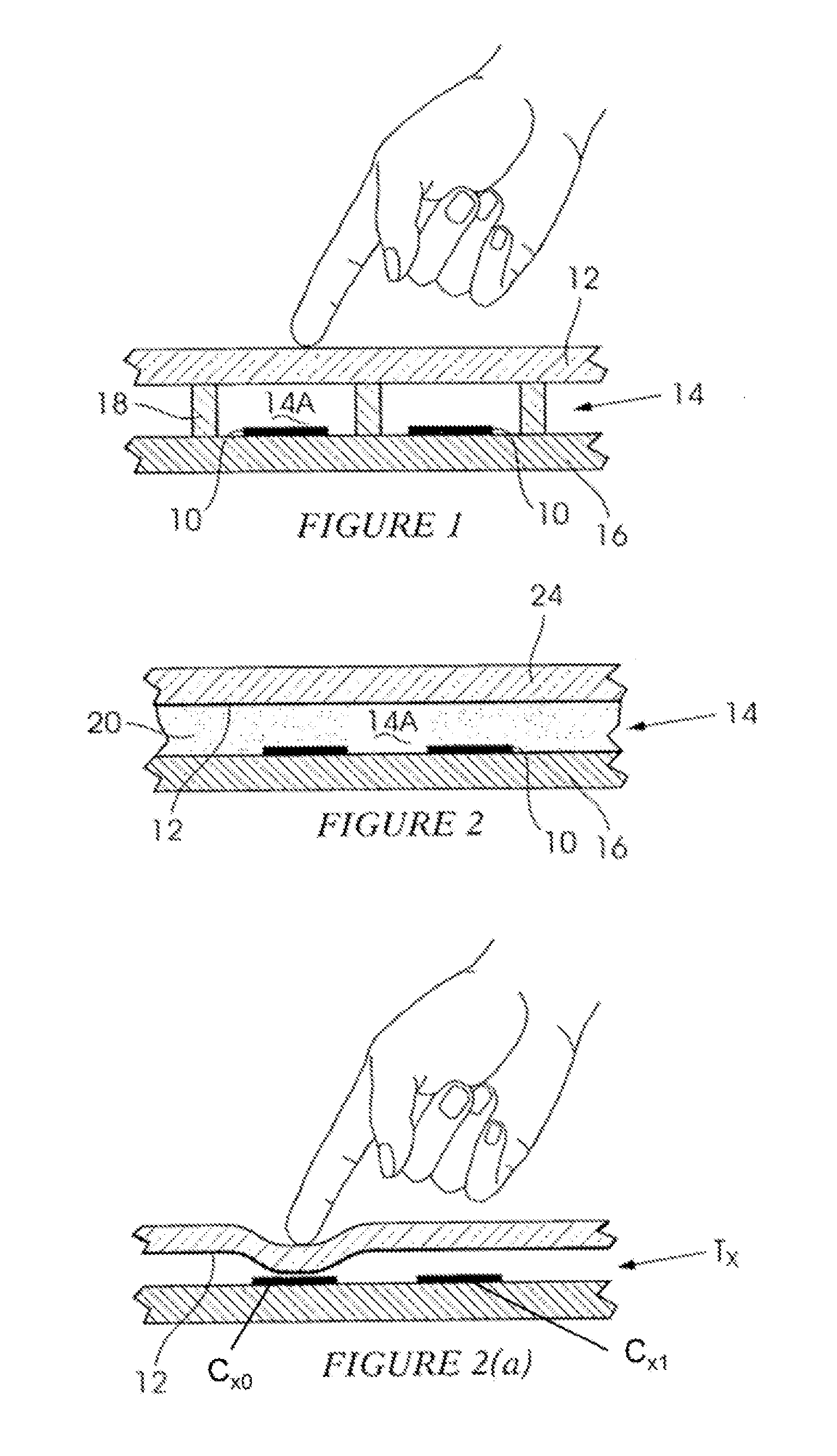
[0079]The construction of such a capacitive sensing, pressure only switch is shown in FIG. 1. A different type of such switch sensor is shown in FIG. 2.

[0080]Normally the designer of a capacitance sensing circuit is advised to keep grounded tracks and surfaces away from the sense plate in order to prevent large capacitance forming to ground and hence resulting in a loss of sensitivity.

[0081]However, due to Azoteq's parasitic capacitance cancellation technology, the ...


PUM


Abstract

A user interface which includes a capacitive measurement circuit with a sense plate covered by an electrically conductive cover member, and wherein said circuit may sense two types of events, said types distinguished by an inverse change in measured capacitance, and wherein user proximity and touches with less than a minimum required force constitute one event type, and touches with more than said minimum force constitute the other event type.

Description

BACKGROUND OF THE INVENTION[0001]This invention relates generally to the construction of pressure-dependent capacitive sensing switches.[0002]Capacitive sensing technology has become popular for use in touch switches covering contact, non-contact and two-dimensional user interface implementations.[0003]As in most technologies, capacitive sensing technologies have strong points like cost, easy form factor integration, and selectable or adjustable force (contact) operation. These technologies also work with various overlay materials. The technology has become popular for user interface implementation, arguably since the year 2000. Various different implementations are used (see products from Cypress, Atmel, Microchip and Azoteq) and capacitive sensors feature in several trend-setting products (e.g. the iPod® and the iPhone® from Apple).[0004]At present however capacitive sensing is seen as lacking certain features that are promoted as being the strength areas of inductive sensing tech...

Claims


Application Information

Patent Timeline
IPC IPC(8): H03K17/96
CPCH03K17/955H03K17/962H03K2217/960755H03K17/9622H03K2217/94036H03K17/975G06F3/0445G06F2203/04105
Inventor BRUWER, FREDERICK JOHANNES
Owner AZOTEQ HLDG LTD
Learn More