Control methods for LED chains

Inactive Publication Date: 2013-04-18
LEADTREND TECH
View PDF13 Cites 8 Cited by
  • Summary
  • Abstract
  • Description
  • Claims
  • Application Information

AI Technical Summary

Benefits of technology

The patent text describes a control method for driving multiple LED chains. The method includes detecting the LED chains to regulate their output power, controlling the driving currents flowing through the LED chains, detecting any under-current events (when a LED chain encounters a lower level of current than normal), stopping short protections applied to the LED chains if such an event occurs, detecting if the output power reaches a safe level, and resuming the short protection of a normal LED chain after the output power reaches the safe level. This approach helps to maintain a safe and stable light emission from the LED chains.

Problems solved by technology

However, open protection and short protection may interfere with each other, so that an appropriate length sequence for activating or disabling open protection and short protection is needed to realize the actual protection effect desired.

Method used


Image

  • Control methods for LED chains
  • Control methods for LED chains
  • Control methods for LED chains

Examples


Embodiment Construction

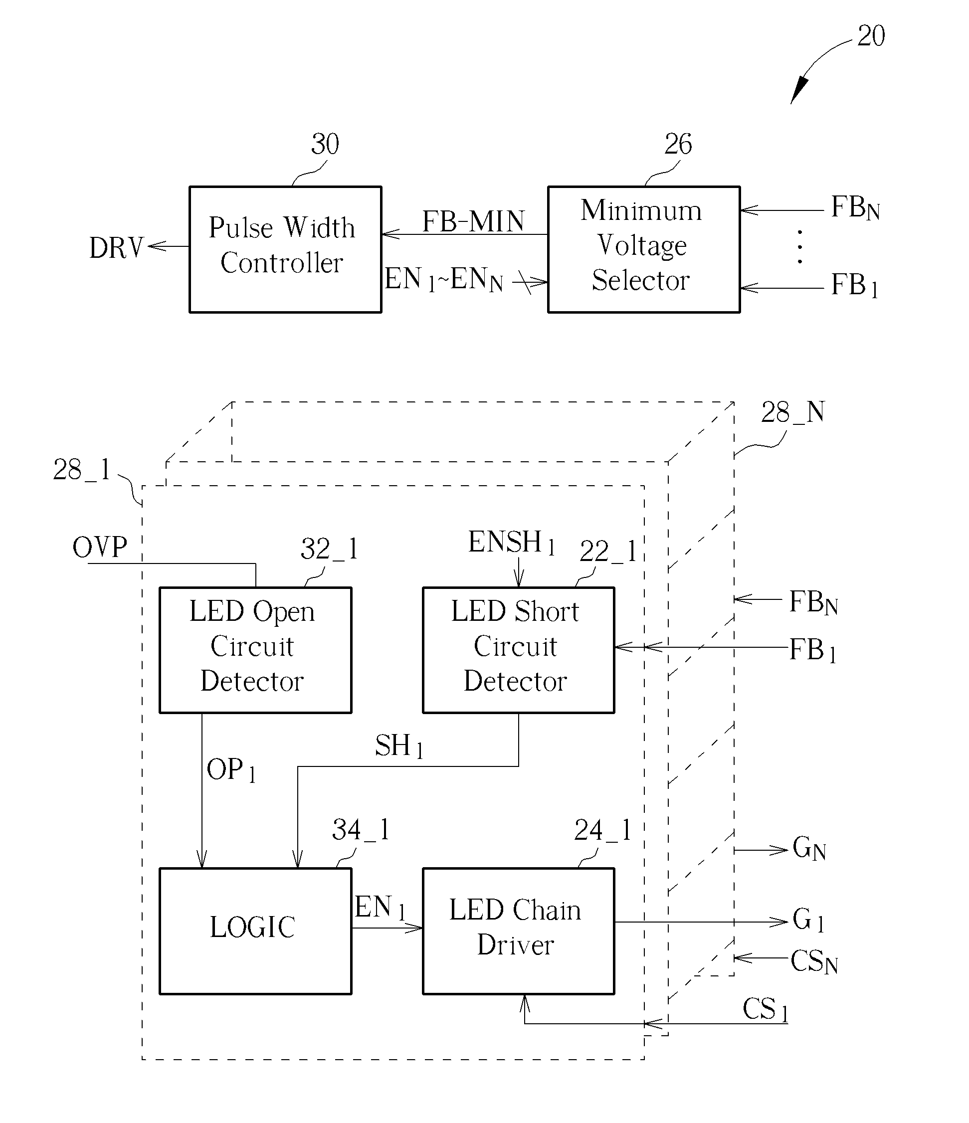
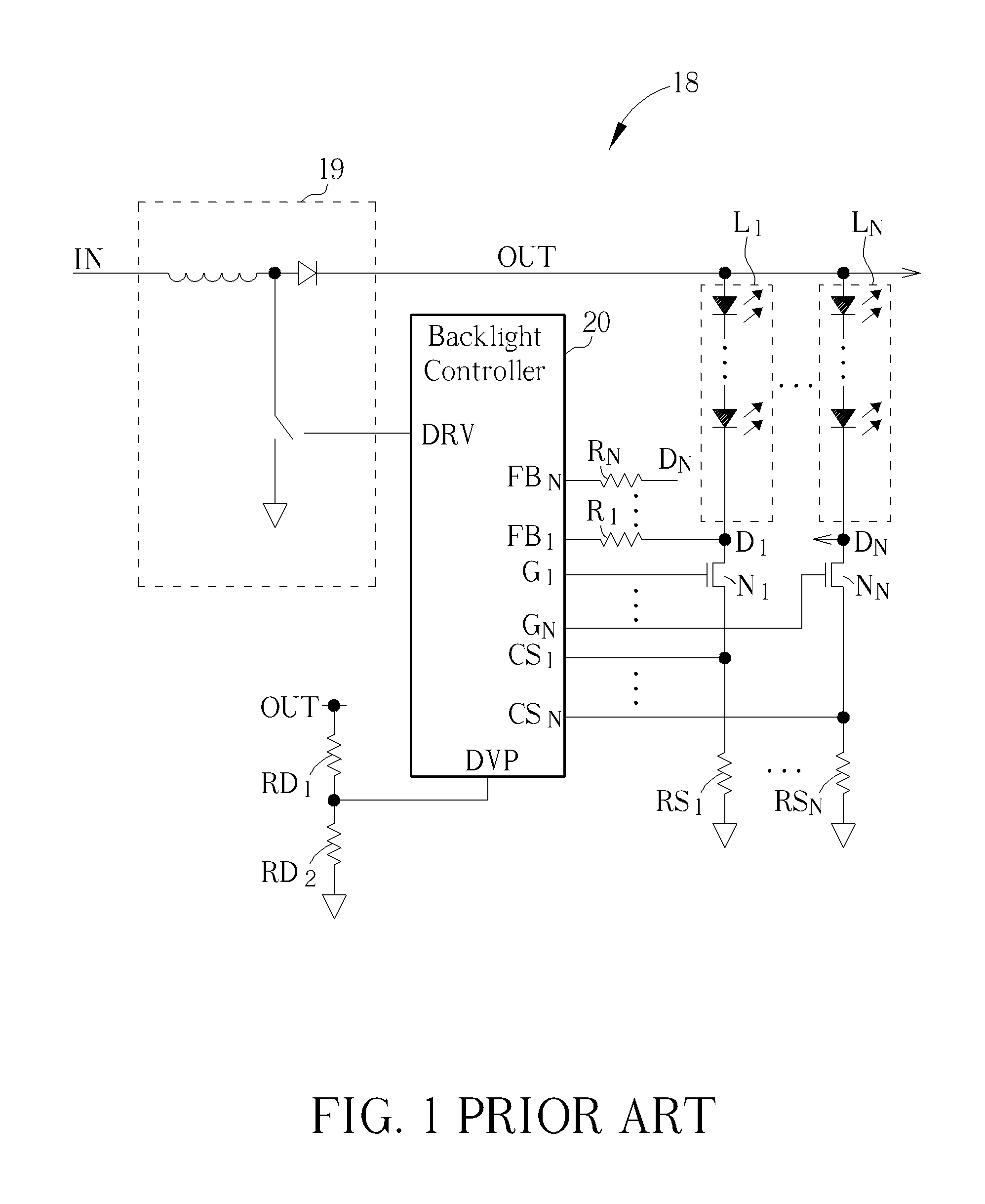
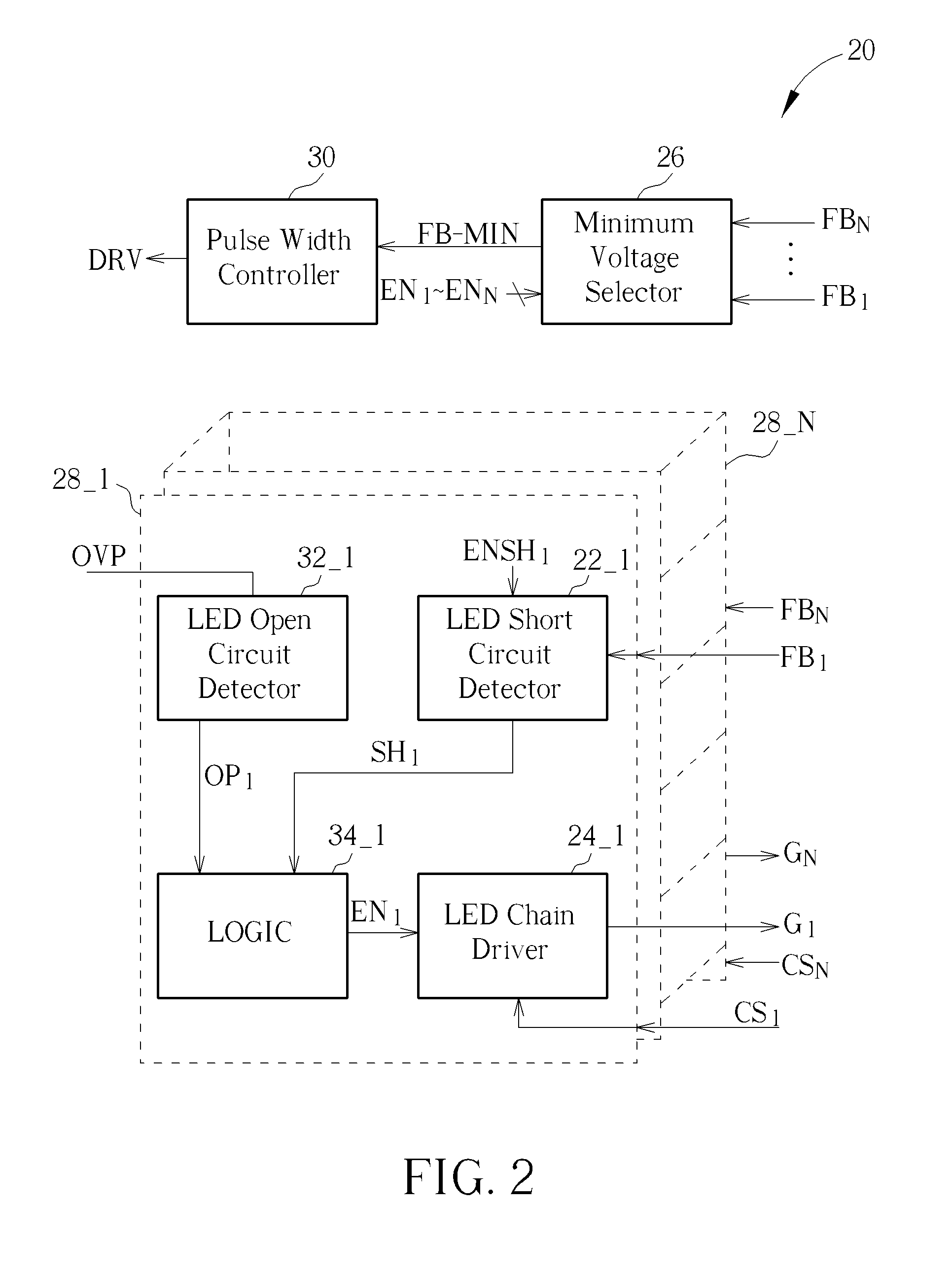
[0016]FIG. 2 is a diagram of backlight controller 20 according to an embodiment. Backlight controller 20 controls NMOS transistors N1-NN through gates G1-GN. Driving current flowing through NMOS transistors N1-NN can be sensed roughly from current sense nodes CS1-CSN. Backlight controller 20 also controls power switch of booster 19 from driving node DRV to cause inductor thereof to charge or discharge. In some embodiments, backlight controller 20 is a monolithic integrated circuit.

[0017]As shown in FIG. 2, backlight controller 20 comprises pulse width controller 30, minimum voltage selector 26, and a plurality of driving modules 281-28N.

[0018]Minimum voltage selector 26 may generate minimum feedback voltage VFB-MIN on minimum feedback node FB-MIN according to the minimum value of feedback voltages VFB-1-VFB-N on feedback nodes FB1-FBN. Pulse width controller 30 controls power switch of booster 19 from driving node DRV to cause voltage VOUT on output node OUT to increase or decrease,...


PUM


Abstract

Control methods for driving LED chains. An output power is provided to drive the LED chains. Short protections are provided to the LED chains, respectively. Whether at least one of the LED chains encounters an under-current event is detected. If any one of the LED chains encounters the under-current event, all short protections are stopped. Whether the output power reaches safe requirement is detected. After the output power reaches the safe requirement, the short protection corresponding to a normal LED chain is resumed. The normal LED chain refers to one of the LED chains that does not encounter the under-current event.

Description

BACKGROUND OF THE INVENTION[0001]1. Field of the Invention[0002]The present invention relates to control methods and control circuits for light-emitting diode (LED) chains, and particularly to a control method for performing short protection in LED chains.[0003]2. Description of the Prior Art[0004]In an age concerned with energy conservation and carbon reduction, light-emitting diodes (LEDs) are already a widely adopted light source due to their superior lighting efficiency and miniature component size. For example, LEDs have already replaced cold-cathode fluorescent lamps (CCFLs) as a backlight in current liquid crystal display (LCD) panels.[0005]FIG. 1 is a diagram illustrating an LED power supply 18 used in a backlight module of an LCD panel, which is primarily used to control lighting of LED chains L1-LN. Each LED chain has a plurality of series-connected LEDs. Backlight controller 20 controls a power switch of booster 19 to cause an inductive element to draw energy from input n...

Claims


Application Information

Patent Timeline
Patent Type & Authority Applications(United States)
IPC IPC(8): H05B37/03
CPCH05B33/0827Y02B20/341H05B33/0887H05B45/46Y02B20/30H05B45/52H05B45/38H05B45/395
Inventor LEE, CHING-TSAN
Owner LEADTREND TECH
Why Eureka
Try Eureka