
Inner rotor-type permanent magnet motor

a permanent magnet motor and rotor-type technology, which is applied in the direction of magnetic circuits characterised by magnetic materials, electrical apparatus, dynamo-electric machines, etc., can solve the problems of insufficient assembly precision of magnetic poles, difficult to stably reduce cogging torque, and displaced magnetic poles in the circumferential direction, so as to improve rotational performance and reduce cogging torque. , the effect of increasing the (bh)max of the magn

Inactive Publication Date: 2013-04-11
MINEBEA CO LTD
View PDF5 Cites 23 Cited by
  • Summary
  • Abstract
  • Description
  • Claims
  • Application Information

AI Technical Summary

Benefits of technology

The present invention provides a structure for an inner rotor-type permanent magnetic motor that allows for the use of ring-shaped magnetic poles that are oriented in a radially oriented magnetic field by a repulsive magnetic field. This structure also reduces the distortion rate of the back-EMF waveform, resulting in a sinusoidal wave shape and reduced harmonic wave components. Additionally, the structure maintains smooth rotation of the motor and enhances the rotational performance by increasing the (BH)max of the magnet. This invention is particularly useful for motors of approximately 50 W or less in terms of power conservation, resource conservation, size reduction, and noise reduction.

Problems solved by technology

The technical problem addressed in this patent relates to reducing cogging torque in an inner rotor-type permanent magnet motor without compromising its efficiency and control ability. This issue arises due to the interaction between the slot design and the high value of the motor's magnet. Various methods such as skewing the magnetic poles or controlling their anisotropy are proposed to address this challenge.

Method used


Image

  • Inner rotor-type permanent magnet motor
  • Inner rotor-type permanent magnet motor
  • Inner rotor-type permanent magnet motor

Examples


embodiments

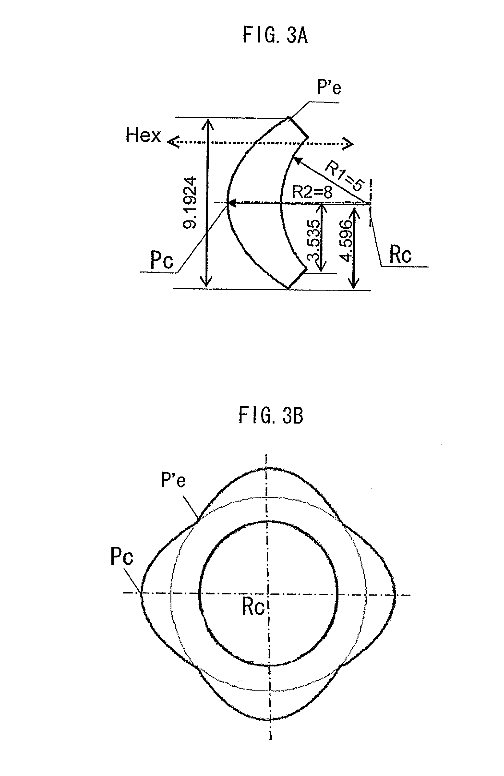
[0038]Hereinafter, embodiments regarding minimizing the cogging torque and the back-EMF in an inner rotor-type permanent magnet motor made from annular magnetic poles where the number of pole pairs Pn is 2 according to the present invention will be explained in more detail. However, the present invention is not limited to the following embodiments.

[0039]A material composition of the magnet according to the present embodiment is as follows (the units in the following are vol. %): 32.1 of an anisotropic Sm2Fe17N3-type fine powder having a grain diameter of 3 to 5 μm and a (BH)max of 290 kJ / m3, 48.9 of anisotropic Nd2Fe14B-type particles having a grain diameter of 38 to 150 μm and a (BH)max of 270 kJ / m3, 6.2 of a novolac-type epoxy oligomer, 9.1 of linear polyamide, 1.8 of 2-phenyl-4,5-dihidroxy methyl imidazole, and 1.9 of a lubricant (pentaerythritol stearic acid triester).

[0040]The magnet in the present embodiment as described above has the following characteristics: a remanence Mr ...


PUM


Abstract

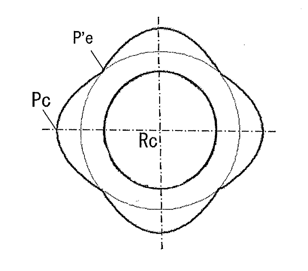
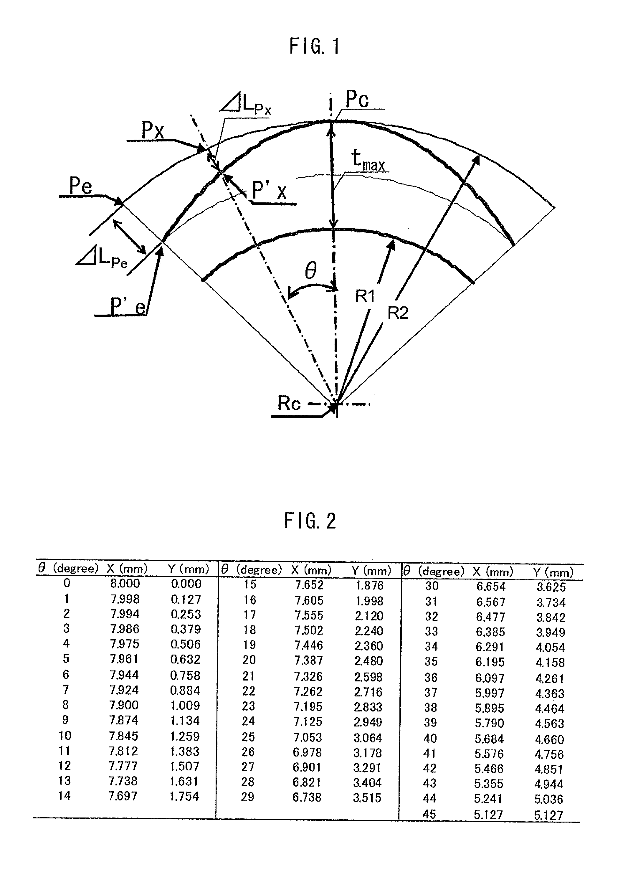
A motor includes poles P having a remanence Mr of 0.9 T or more, a coercivity HcJ of 0.80 MA/m or more, and a maximum energy product (BH)max of 150 kJ/m3 or more, which sets a center point Pc of the magnetic poles in a circumferential direction on a rotor outer circumferential surface to a maximum thickness tmax, wherein when a line connecting the Pc and a rotational axis center Rc is Pc-Rc, a straight line connecting an arbitrary point Px in the circumferential direction on the rotor outer circumferential surface and the Rc is Px-Rc, an apex angle of the lines Pc-Rc and Px-Rc is θ, a number of pole pairs is Pn, a circumferential direction magnetic pole end is Pe, and a magnetic pole end biasing distance ΔLPe of the circumferential direction magnetic pole ends Pe is α×tmax (α is a coefficient).

Description


Claims


Application Information

Patent Timeline
Owner MINEBEA CO LTD
Learn More