Scintillator material and scintillation detector

a scintillator and material technology, applied in the direction of instruments, conversion screens, nuclear engineering, etc., can solve the problem that the generation pet devices require high time resolution, and achieve the effect of shortening the fluorescence lifetim

Inactive Publication Date: 2013-04-11
DAISHINKU CORP
View PDF2 Cites 2 Cited by
  • Summary
  • Abstract
  • Description
  • Claims
  • Application Information

AI Technical Summary

Benefits of technology

[0019]The present invention provides a scintillator material of a shorter fluorescence lifetime and provides a scintillation detector that includes a scintillator made of the scintillator material.

Problems solved by technology

These next generation PET devices require high time resolution, which necessitates scintillators of particularly short fluorescence lifetime.

Method used


Image

  • Scintillator material and scintillation detector
  • Scintillator material and scintillation detector
  • Scintillator material and scintillation detector

Examples


examples

[0040]Description will be made below with regard to fluorescence characteristics of scintillator materials according to examples 1 to 6 of the embodiment produced by the above-described method for production, by way of comparison with conventional scintillator materials according to comparative examples 1 to 6.

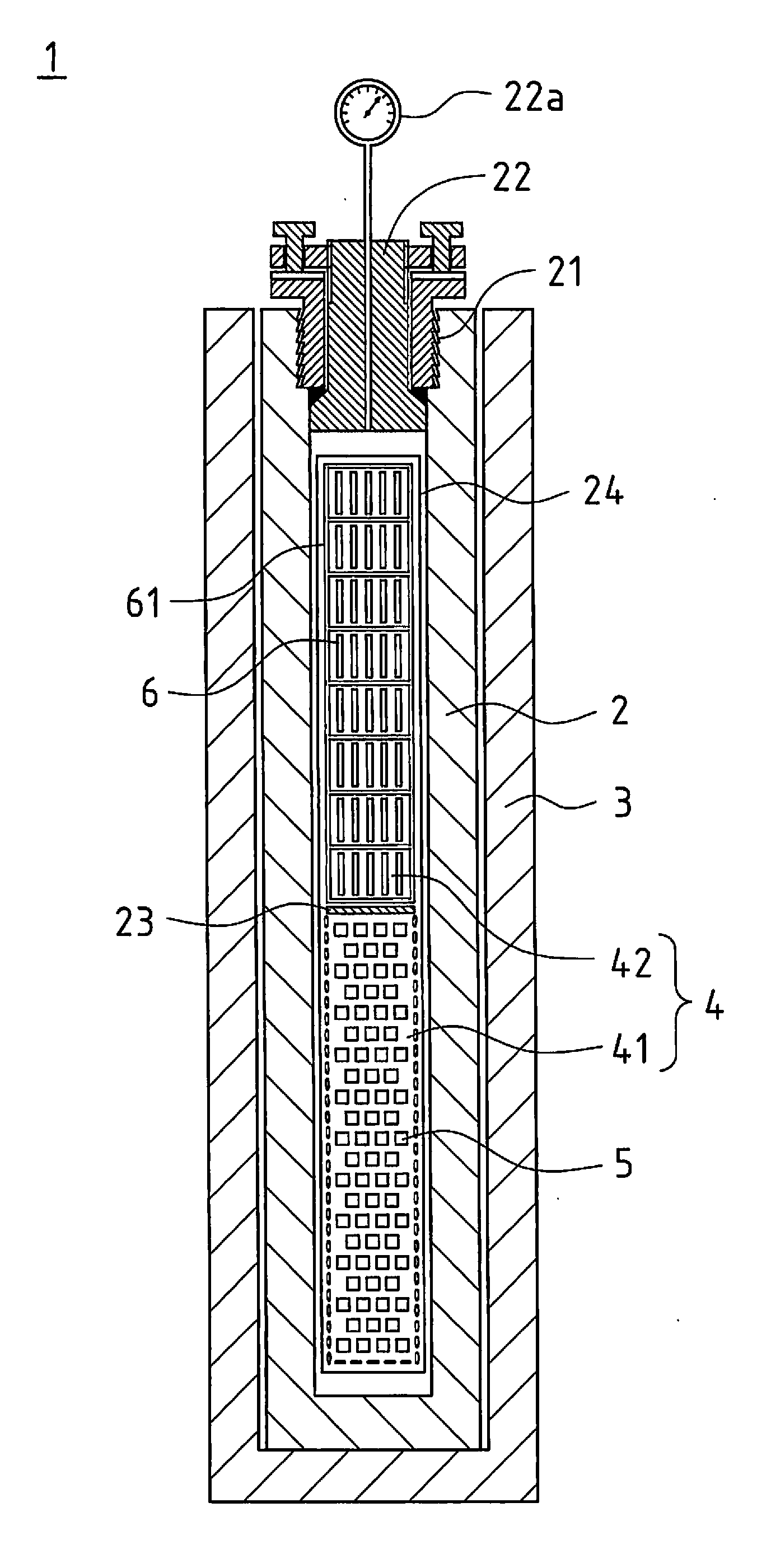
[0041]The scintillator materials according to comparative examples 1 to 6 are each made of a zinc-oxide single crystal grown on an M surface, which is a main surface, of a seed crystal. Specifically, the seed crystal 6 used was a plate-shaped zinc-oxide single crystal with an M surface as a main surface. The plate-shaped zinc-oxide single crystal was cut from a hexagonal crystal with the M surface in parallel to a (10-10) surface, which is an M surface of the hexagonal crystal. A zinc-oxide single crystal was obtained by the above-described method for production, and the obtained zinc-oxide single crystal was cut to remove a part grown on the M surface. This part of the zinc-o...


PUM

PropertyMeasurementUnit
fluorescence lifetimeaaaaaaaaaa
diameteraaaaaaaaaa
diameteraaaaaaaaaa

Abstract

A scintillator material is made of a zinc-oxide single crystal grown on a +C surface or a −C surface of a plate-shaped seed crystal of zinc oxide including a C surface as a main surface. The zinc-oxide single crystal contains In and Li. In response to an incident radiation, the scintillator material emits fluorescence of less than 20-ps fluorescence lifetime.

Description

FIELD OF THE INVENTION[0001]The present invention relates to a scintillator material that emits fluorescence in response to an incident radiation. The present invention also relates to a scintillation detector that includes a scintillator made of such scintillator material.TECHNICAL FIELD[0002]Scintillation detectors expose their scintillator to ionization radiation such as X rays, γ rays, and α rays, which causes the scintillator to emit fluorescence. The fluorescence is amplified by a photomultiplier tube for detection.[0003]One application of such scintillation detector is PET (Positron Emission Tomography) devices, which detect γ rays emitted in process of positrons annihilation. PET devices use coincidence to detect γ rays, which are comparatively higher in energy, and for this purpose, employ scintillation detectors that are high in sensitivity and in response speed.[0004]In recent years, attempts are underway to develop next generation PET devices of TOF (Time-Of-Flight) type...

Claims


Application Information

Patent Timeline
Patent Type & Authority Applications(United States)
IPC IPC(8): G01T1/202
CPCC09K11/623C30B7/10C30B29/16G21K4/00C09K11/55G01T1/2023C09K11/54G01T1/202G01T1/003G21K2004/06
Inventor KANO, MASATAKAWAKAMIYA, AKIRAYAMANOI, KOHEISHIMIZU, TOSHIHIKOSARUKURA, NOBUHIKOEHRENTRAUT, DIRKFUKUDA, TSUGUO
Owner DAISHINKU CORP
Why Eureka
Try Eureka