
Display device and assembling method thereof

a display device and assembly method technology, applied in the direction of instruments, computing, electrical apparatus casings/cabinets/drawers, etc., can solve the problem of limiting the low-profile design of the display device, and achieve the effect of reducing thickness and width, facilitating low-profile and lightweight designs, and reducing overall structure thickness

Inactive Publication Date: 2013-03-28
COMPAL ELECTRONICS INC
View PDF13 Cites 9 Cited by
  • Summary
  • Abstract
  • Description
  • Claims
  • Application Information

AI Technical Summary

Benefits of technology

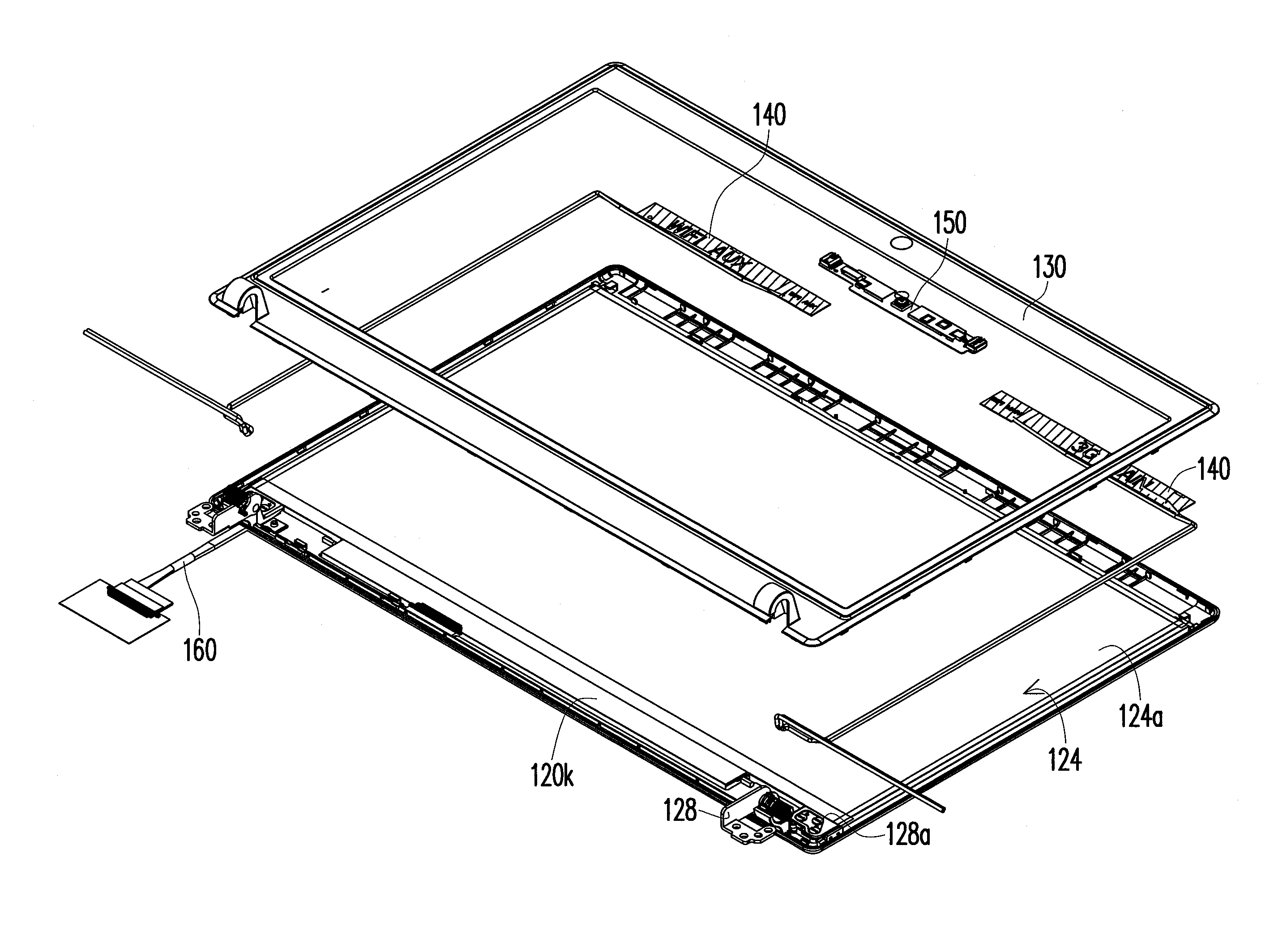
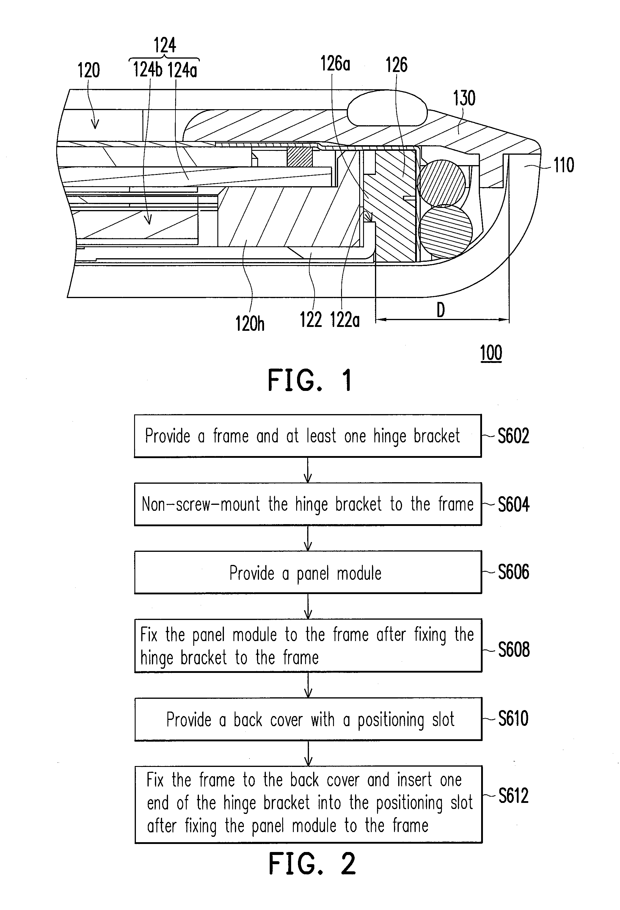
The present invention relates to a display device with a reduced thickness and width, achieved by eliminating the need for screw-mounting of the hinge bracket onto the first frame. This design allows for a thicker and wider display device to be assembled without compromising its strength. Additionally, the hinge bracket can be mounted onto the end of the first frame during assembly, further reducing the overall structure width. Inserting the hinge bracket into the positioning slot of the back cover can further solidify the overall structure and reduce the space occupied by the hinge bracket in the display device.

Problems solved by technology

In order to provide the room for screw-mounting, the display device must have sufficient thickness and width, which limits the low-profile design of the display device.

Method used


Image

  • Display device and assembling method thereof
  • Display device and assembling method thereof
  • Display device and assembling method thereof

Examples


Embodiment Construction

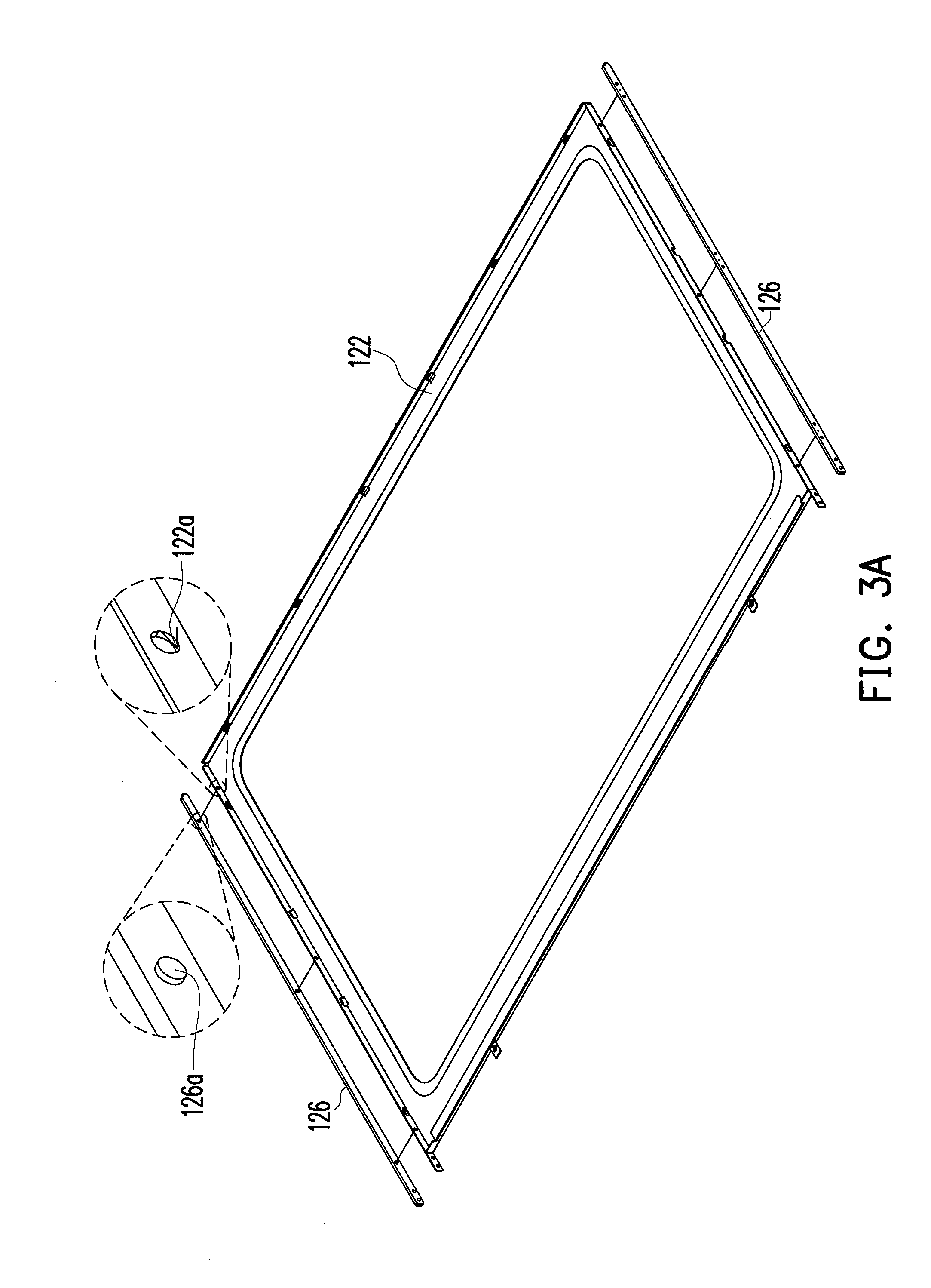
[0038]FIG. 1 is a partial, cross-sectional view of a display device according to one embodiment of the present invention. FIG. 2 is a flow chart of assembly of the display device of FIG. 1. FIG. 3A to FIG. 3N illustrate assembly steps of the display device of FIG. 1. Referring to FIG. 2 and FIG. 3A, a first frame 122 and at least one hinge bracket 126 are provided (step S602). Referring to FIG. 2 and FIG. 3B, the hinge bracket 126 is screwless-mounted to the first frame 122 (step S604). For example, the hinge bracket 126 may be fixed to the first frame 122 with adhesive or by soldering. However, it is not intended to limit the mounting to any particular manner. In another embodiment, the hinge bracket 126 may be fixed to the first frame 122 in another suitable screwless-mounting manner.

[0039]Referring to FIG. 1 and FIG. 3A, in the present embodiment, the first frame 122 includes at least one positioning hole 122a, the hinge bracket 126 includes at least one positioning post 126a, an...


PUM

PropertyMeasurementUnit
distanceaaaaaaaaaa
sizeaaaaaaaaaa
thicknessaaaaaaaaaa

Abstract

A display device is provided, which includes a back cover and a display module. The back cover has a positioning slot. The display module includes a first frame, a panel module and at least hinge bracket. The first frame is fixed to the back cover. The panel module is fixed to the first frame. The hinge bracket is screwless-mounted to the first frame. One end of the hinge bracket is inserted into the positioning slot to fix the display module to the back cover. Besides, a method for assembling a display device is also provided.

Description

CROSS-REFERENCE TO RELATED APPLICATION[0001]This application claims the priority benefits of U.S. provisional application Ser. No. 61 / 539,473, filed on Sep. 26, 2011. The entirety of the above-mentioned patent applications is hereby incorporated by reference herein and made a part of this specification.BACKGROUND OF THE INVENTION[0002]1. Field of the Invention[0003]The present invention relates to a display device and a method for assembling the display device, and more particularly, to a display device with a hinge bracket and a method for assembling the display device with the hinge bracket.[0004]2. Description of Related Art[0005]Owing to the advancement of semiconductor devices and display technology, electronic products have been continuously developed toward the trend of small size, multi-function and easy carry. Common portable electronic products include notebook computers, tablet computers and mobile phones. Taking a notebook computer as an example, it consists of a host an...

Claims


Application Information

Patent Timeline
Patent Type & Authority Applications(United States)
IPC IPC(8): G06F1/16H05K13/04
CPCG06F1/1637Y10T29/49002G06F1/1681G06F1/1601
Inventor CHEN, PAI-FENGLIN, PO-ANLING, KUO-NANCHEN, YUNG-HUI
Owner COMPAL ELECTRONICS INC
Learn More