Isolated gate driver adapted for pwm-based switching power supply

a technology of isolated gate and switching power supply, which is applied in the direction of power conversion systems, electrical apparatus, transistors, etc., can solve the problem that the high-power mosfet q cannot be reliably driven by the conventional isolated gate driver b, and achieve the effect of duty cycl

Active Publication Date: 2013-03-28
SPI ELECTRONICS +1
View PDF12 Cites 20 Cited by
  • Summary
  • Abstract
  • Description
  • Claims
  • Application Information

AI Technical Summary

Benefits of technology

[0007]In order to solve the problems mentioned in the above “BACKGROUND OF THE INVENTION”, an exemplary embodiment of the invention provides an isolated gate driver including a driving control circuit, an isolated transformer, an anti-circuit and a secondary processing circuit. The driving control circuit is configured to generate a driving pulse-width-modulation (PWM) signal for driving a power switch tube. The isolated transformer has a primary winding and a secondary winding. The anti-circuit is connected between the driving control circuit and the primary winding of the isolated transformer, and is configured to suppress a variation of an induced voltage in the secondary winding of the isolated transformer when a duty cycle of the driving PWM signal is sharply decreased. The secondary processing circuit is connected in parallel with the secondary winding of the isolated transformer, and is configured to perform a voltage clamping action on a gate-source voltage of the power switch tube when the duty cycle of the driving PWM signal is sharply decreased.

Problems solved by technology

Obviously, the high power MOSFET Q cannot be reliably driven by the conventional isolated gate driver 10.

Method used


Image

  • Isolated gate driver adapted for pwm-based switching power supply
  • Isolated gate driver adapted for pwm-based switching power supply
  • Isolated gate driver adapted for pwm-based switching power supply

Examples


Embodiment Construction

[0024]Reference will now be made in detail to the present preferred embodiments of the invention, examples of which are illustrated in the accompanying drawings. Wherever possible, the same reference numbers are used in the drawings and the description to refer to the same or like parts.

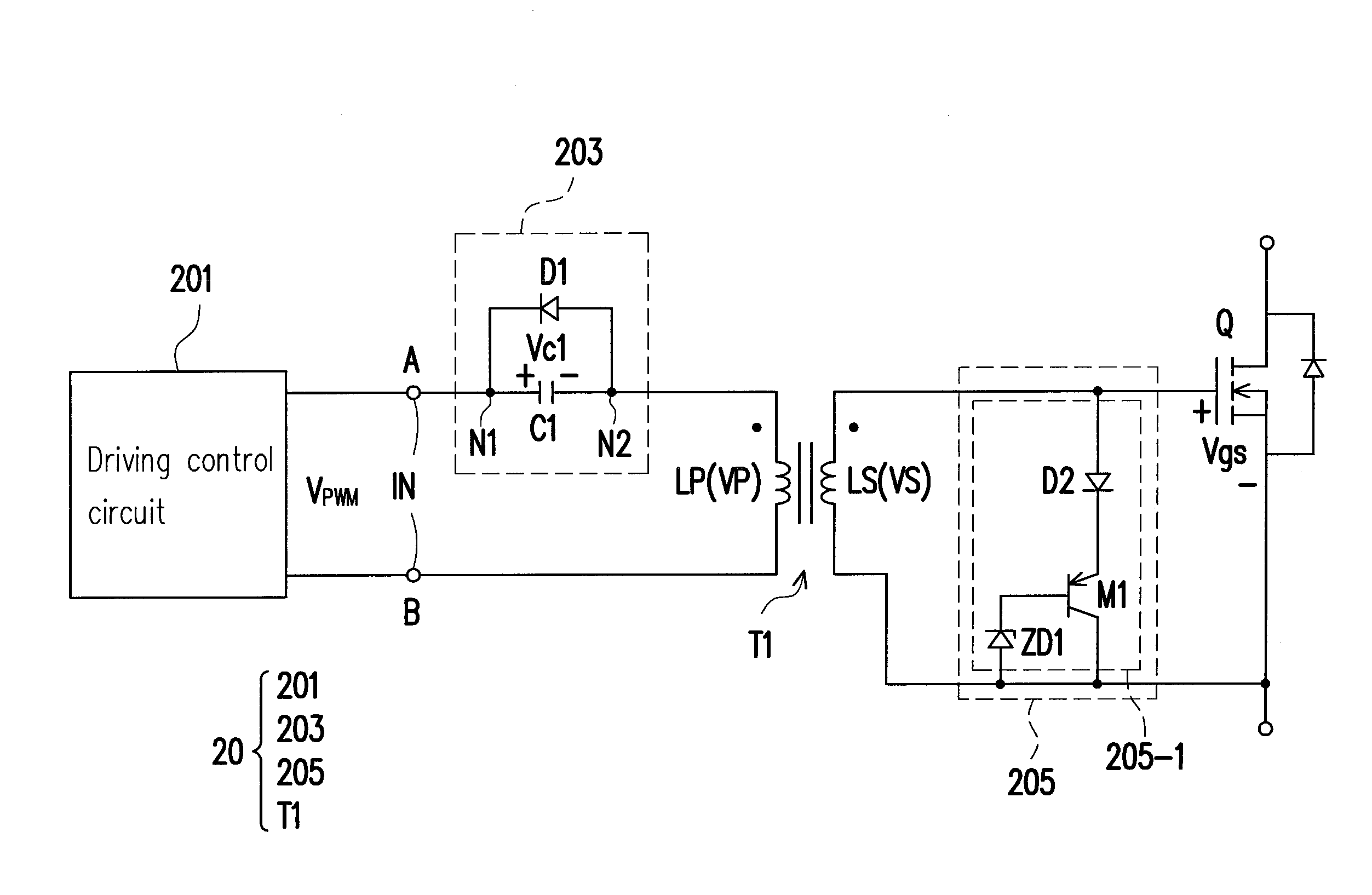
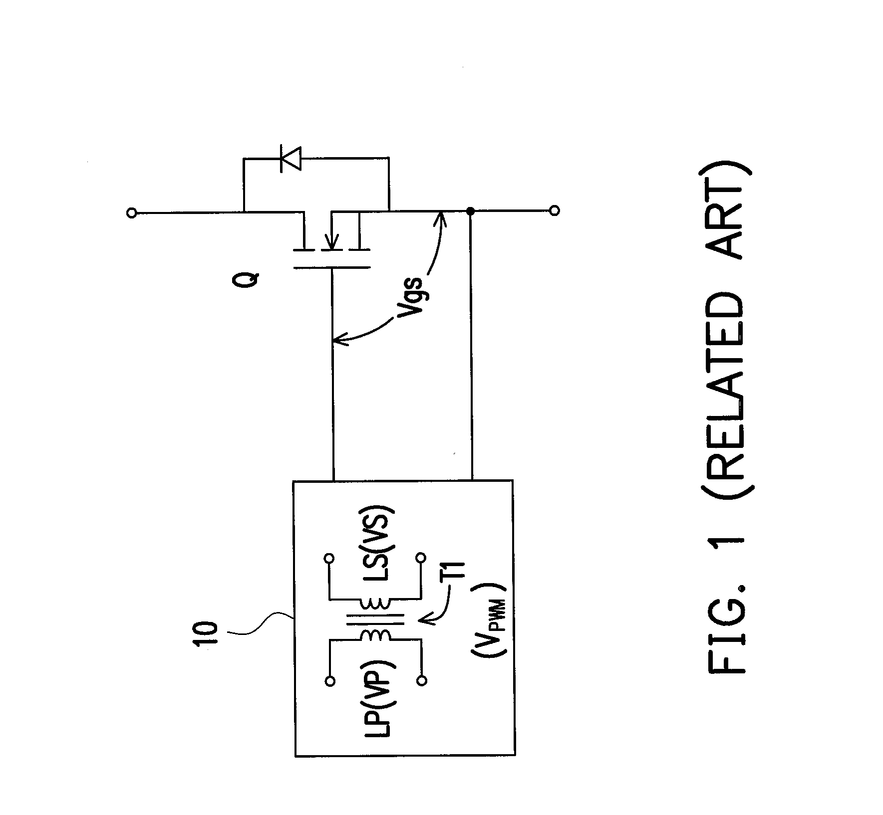
[0025]FIG. 2 is a diagram of an isolated gate driver 20 according to an exemplary embodiment of the invention. Referring to FIG. 2, the isolated gate driver 20 includes a driving control circuit 201, an isolated transformer T1 having a primary winding LP and a secondary winding LS, an anti-circuit 203 and a secondary processing circuit 205. In this exemplary embodiment, the driving control circuit 201 is configured to generate a driving pulse-width-modulation (PWM) signal VPWM for driving a power switch tube Q, where the power switch tube Q may be implemented by a power MOSFET, but not limited thereto. Moreover, the turns ratio (LP / LS) of the isolated transformer T1 can be determined by the real desi...


PUM


Abstract

An isolated gate driver including a driving control circuit, an isolated transformer, an anti-circuit and a secondary processing circuit is provided. The driving control circuit is configured to generate a driving PWM signal for driving a power switch tube. The isolated transformer has a primary winding and a secondary winding. The anti-circuit is connected between the driving control circuit and the primary winding of the isolated transformer, and is configured to suppress a variation of an induced voltage in the secondary winding of the isolated transformer when a duty cycle of the driving PWM signal is sharply decreased. The secondary processing circuit is connected in parallel with the secondary winding of the isolated transformer, and is configured to perform a voltage clamping action on a gate-source voltage of the power switch tube when the duty cycle of the driving PWM signal is sharply decreased.

Description

CROSS-REFERENCE TO RELATED APPLICATION[0001]This application claims the priority benefit of China application serial no. 201110285731.1, filed on Sep. 23, 2011. The entirety of the above-mentioned patent application is hereby incorporated by reference herein and made a part of this specification.BACKGROUND OF THE INVENTION[0002]1. Field of the Invention[0003]The present invention relates to a gate driving technology, more particularly, to an isolated gate driver adapted for, for example, a PWM-based switching power supply.[0004]2. Description of the Related Art[0005]A conventional isolated gate driver 10 as shown in FIG. 1 generally includes an isolated transformer T1, and can be used to drive the high power MOSFET Q connected with the secondary winding LS of the isolated transformer T1 in response to a driving pulse-width-modulation (PWM) signal VPWM. However, assuming that the turns ratio of the isolated transformer T1 is 1:1, so when the duty cycle of the driving PWM signal VPWM ...

Claims


Application Information

Patent Timeline
Patent Type & Authority Applications(United States)
IPC IPC(8): H03K17/691
CPCH02M1/08H02M1/32H03K17/691H03K17/08122H03K17/161
Inventor XU, MINGZHU, JING-PENGSUN, JU-LUNAN, ZHANG-HE
Owner SPI ELECTRONICS
Why Eureka
Try Eureka