
Archery Bow Modular Cam System

a cam system and archery bow technology, applied in the field of archery bows, can solve the problems of not offering the capability of adjusting the draw weight, and the 374 concept is even more complex

Inactive Publication Date: 2013-03-28
MCP IP
View PDF4 Cites 67 Cited by
  • Summary
  • Abstract
  • Description
  • Claims
  • Application Information

AI Technical Summary

Benefits of technology

The patent describes an archery bow with rotatable members and a cam module. The cam module can be adjusted and removed from the bow without precompressing the limbs or relaxing the tension on the bow. The cam module has a hook that engages a portion of the rotatable member body. The technical effect of this design is the ability to create a more efficient and easy-to-use archery bow.

Problems solved by technology

The main short coming of this concept is that each module only provides a single draw force profile capability; therefore it would require a multitude of different designed modules to cover all of the normal draw weight and draw length combinations encountered in market place.
However, the '374 concept is even more complex in that it can require a number of add on plates or modules to arrive at a single given draw force configuration.
While this concept requires only one module on each cam that is not readily replaceable or subject to loss, the resulting system is limited in that it does not offer draw weight change capability.

Method used


Image

  • Archery Bow Modular Cam System
  • Archery Bow Modular Cam System
  • Archery Bow Modular Cam System

Examples


Embodiment Construction

[0055]While this invention may be embodied in many different forms, there are described in detail herein specific embodiments of the invention. This description is an exemplification of the principles of the invention and is not intended to limit the invention to the particular embodiments illustrated.

[0056]For the purposes of this disclosure, like reference numerals in the figures shall refer to like features unless otherwise indicated.

[0057]The archery bow concept described herein presents a new dimension in cam design that incorporates the use of a limited number of adjustable cam modules to provide a wide variety of compound bow offerings.

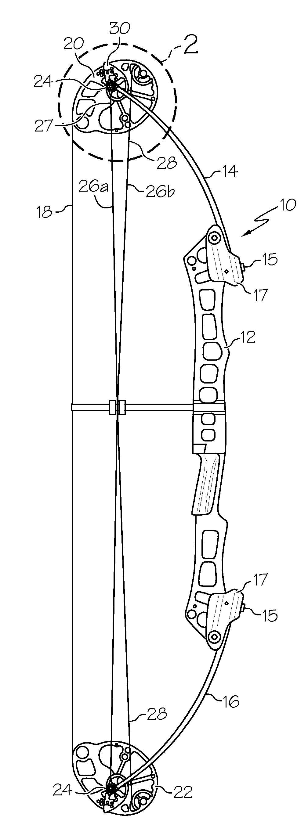
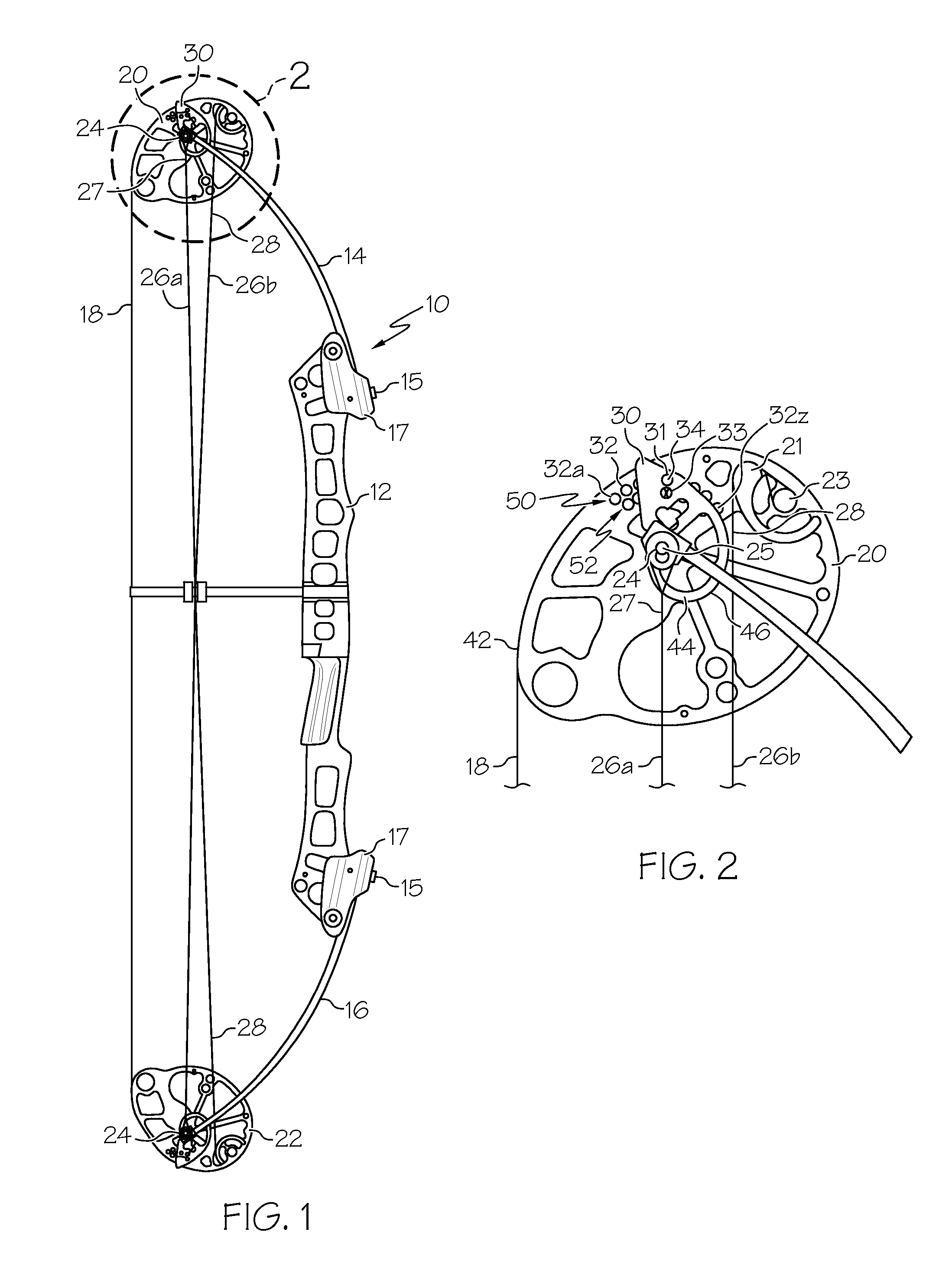
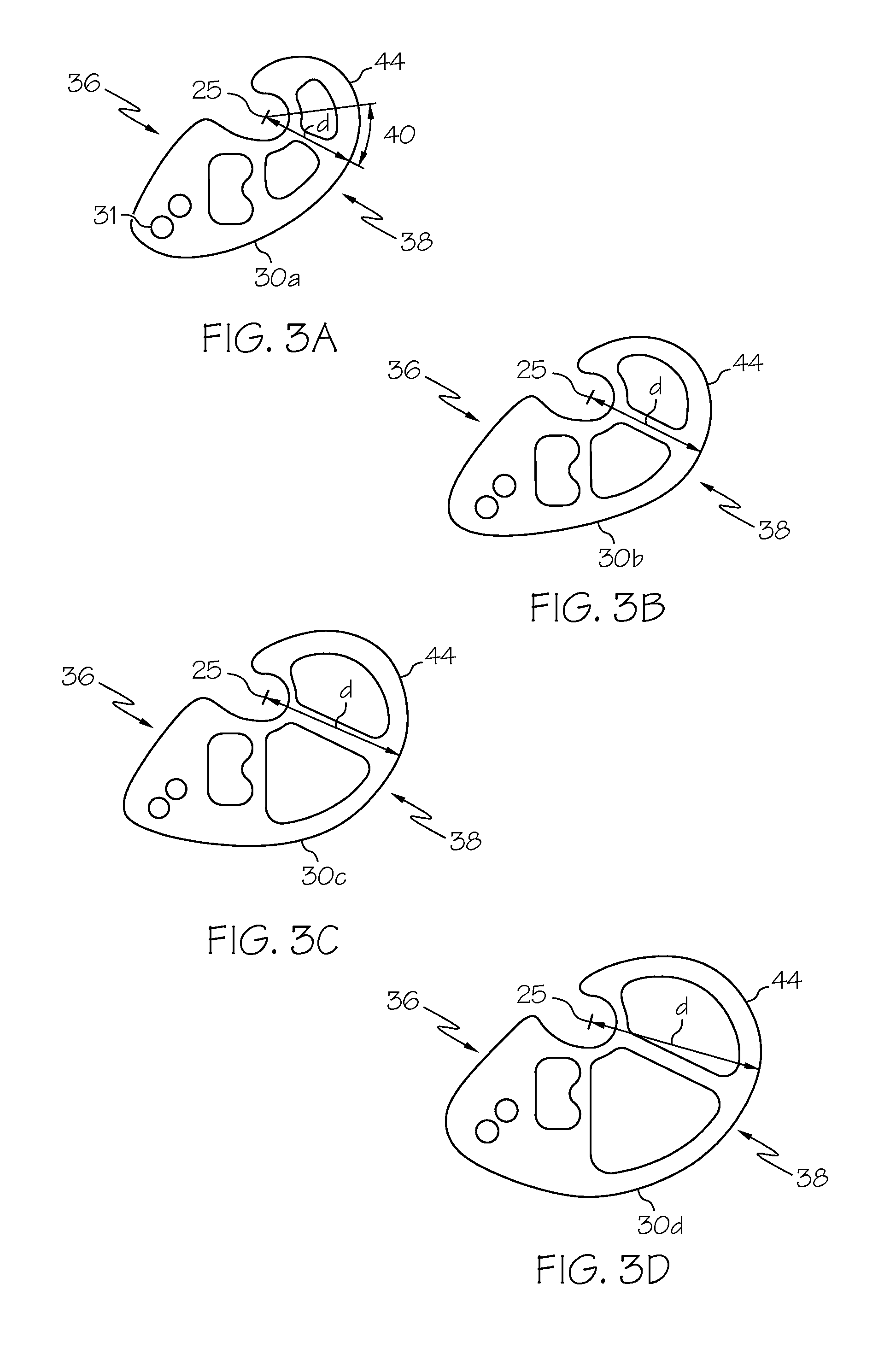
[0058]FIG. 1 shows an embodiment of a bow 10 that comprises a riser 12 that supports a first limb 14 and a second limb 16. Each limb 14, 16 is attached to the riser 12 with a fastener 15 (e.g., limb bolt), and may also be held by a limb cup 17. The first limb 14 supports a first rotatable member 20 and the second limb 16 supports a second rotat...


PUM


Abstract

A modular cam system for an archery bow or crossbow includes swappable cams that change the maximum draw weight of the archery bow or crossbow. Moreover, the modular cams can be affixed to a rotatable member in a number of orientations to set the desired draw length without changing the limbs, tightening or loosening limb bolts, or disassembling the bow. Further, the maximum draw weight of the bow remains substantially similar throughout a large portion of the draw length adjustment for a specified cam module.

Description

CROSS-REFERENCE TO RELATED APPLICATIONS[0001]This Application claims priority to U.S. Provisional Application No. 61 / 539,885, filed Sep. 27, 2011, the entire contents of which are hereby incorporated by reference.BACKGROUND OF THE INVENTION[0002]This invention relates generally to archery bows and more specifically to compound bows having cam adjustability.[0003]Various types of compounding archery bows are generally known in the art. Compounding archery bows generally include a plurality of rotatable members, at least one of which comprises a cam. The cam desirably provides for a reduction in the draw weight when the bow is fully drawn, allowing an archer to hold the bow in a drawn position with less fatigue.[0004]Some compounding bows include at least one rotatable member having a cam, wherein at least a portion of the cam is either adjustable with respect to the rest of the rotatable member or can be removed entirely and replaced with another cam module having a different shape.[...

Claims


Application Information

Patent Timeline
IPC IPC(8): F41B5/10
CPCF41B5/105
Inventor MCPHERSON, MATHEW A.
Owner MCP IP
Learn More