Quick Release Fastening System

Active Publication Date: 2013-03-28
ROBINS TERRY K
View PDF5 Cites 26 Cited by
  • Summary
  • Abstract
  • Description
  • Claims
  • Application Information

AI Technical Summary

Benefits of technology

[0004]The following presents a simplified summary of the invention in order to provide a basic understanding of some aspects of the invention. This summary is not an extensive overview of the invention. It is not intended to identify critical elements of the invention or to delineate the scope of the invention. Its sole purpose is to present some concepts of the invention in a simplified form as a prelude to the more detailed description that is presented elsewhere.
[0005]In one embodiment, a locking device includes first and second legs operatively coupled to one another to form a perimeter substantially uninterrupted from a proximal end of the first leg to a proximal end of the second leg. The first leg proximal end and the second leg proximal end are separated by an opening, and the first leg proximal end and the second leg proximal end each respectively defining a passage. The first leg proximal end has a keyway extending from the first leg passage, and the first leg proximal end has first and second shoulders adjacent the keyway. The second leg proximal end has a receiving area extending from the second leg passage. A locking pin passes through the second leg passage. The locking pin has a key and a stop that prevent the locking pin from passing entirely through the second leg passage such that the locking pin is inseparable from the second leg proximal end. The locking pin has first and second ends, and the key is at the locking pin first end. The locking pin is movable between an open position wherein the opening is generally unobstructed and the key is seated in the receiving area, a closed position wherein the opening is obstructed by the locking pin and the key is seated against the first leg proximal end with the first and second shoulders preventing the key from reaching the keyway, and an intermediate position wherein the key extends beyond the first and second shoulders to access the keyway. A biasing member is included that biases the locking pin such that the key seats against the first leg proximal end when the locking pin is at the closed position, such that the key passes at least partially through the keyway when the locking pin is at the intermediate position and the key is aligned with the keyway, and such that the locking pin moves to the closed position when the locking pin is at the intermediate position and the key is aligned distinctly from the keyway and the first and second shoulders.
[0006]In another embodiment, a locking device includes first and second legs operatively coupled to one another to form a perimeter substantially uninterrupted from a proximal end of the first leg to a proximal end of the second leg. The first leg proximal end and the second leg proximal end are separated by an opening, and the first leg proximal end and the second leg proximal end each respectively define a passage along a common imaginary axis. The first leg proximal end has a first side relatively adjacent to the second leg and a second side relatively distant from the second leg. Moreover, the first leg proximal end has a keyway extending from the first leg passage, and the first leg proximal end has first and second shoulders adjacent the keyway at the second side. A locking pin passes through the second leg passage. The locking pin has a key and a stop that prevent the locking pin from passing entirely through the second leg passage such that the locking pin is inseparable from the second leg proximal end. The locking pin has first and second ends, and the key is at the locking pin first end. The locking pin is movable between an open position wherein the opening is at least partially unobstructed, a closed position wherein the opening is completely obstructed by the locking pin and the key is seated against the first leg proximal end with the first and second shoulders preventing the key from reaching the keyway, and an intermediate position wherein the key extends beyond the first and second shoulders to access the keyway. A biasing member is included that biases the locking pin such that the key seats against the first leg proximal end when the locking pin is at the closed position, such that the key passes at least partially through the keyway when the locking pin is at the intermediate position and the key is aligned with the keyway, and such that the locking pin moves to the closed position when the locking pin is at the intermediate position and the key is aligned distinctly from the keyway and the first and second shoulders.

Problems solved by technology

Drawbacks remain in prior art shackles, however (e.g., complications in manufacturing, difficulties in use, attention that must be paid not to clog relatively small openings in locking pins, etc.), and new quick release fastening systems that may overcome some of these and / or other deficiencies are desirable.

Method used


Image

  • Quick Release Fastening System
  • Quick Release Fastening System
  • Quick Release Fastening System

Examples


Embodiment Construction

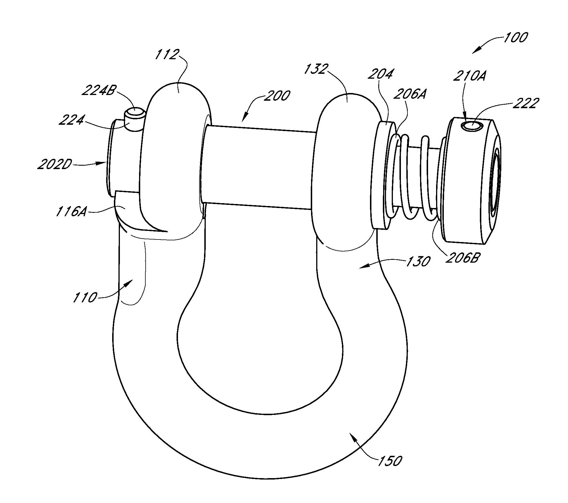
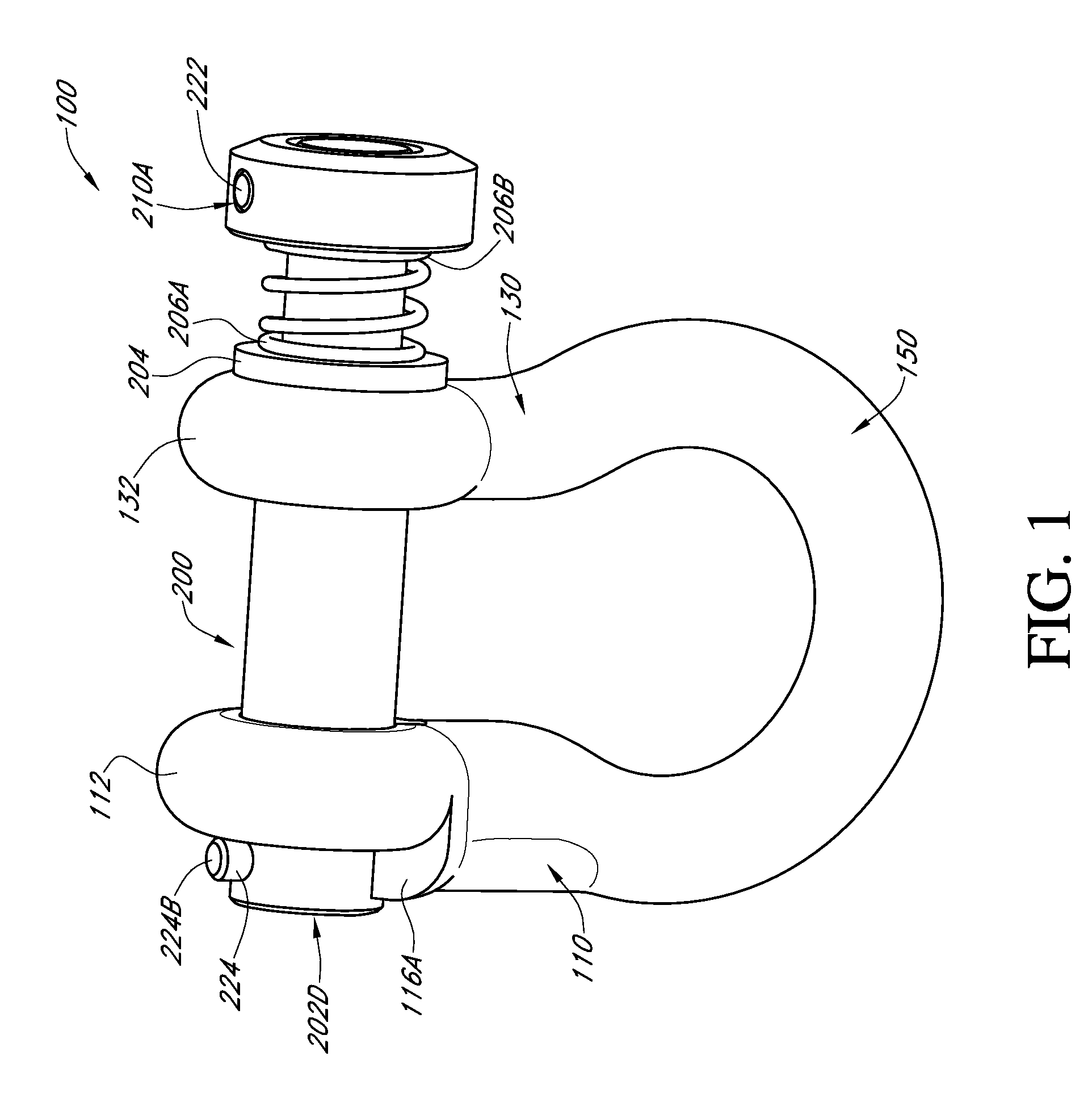
[0020]Embodiments of the present invention provide systems and methods for quickly and conveniently securing two or more objects to each other. FIG. 1 shows one embodiment 100 of a quick release fastener in accordance with the teachings of the current invention. As can be seen, the quick release fastener 100 has a first leg 110, a second leg 130, a connecting member 150, and a closure element (or “locking pin”) 200.

[0021]The first leg 110 and the second leg 130 are connected to each other (e.g., at respective distal ends) by the connecting member 150. The legs 110, 130 and the connecting member 150 are shown in the drawings as collectively being C-shaped. People of skill in the art will appreciate however that the elements may be of other shapes so long as a substantially uninterrupted perimeter is formed from a proximal end of the first leg to a proximal end of the second leg (e.g., U-shaped). The connecting member 150 may be made of wrought iron, galvanized carbon steel, metal all...


PUM


Abstract

Locking devices as well as methods of their manufacture and use are disclosed. One locking device includes first and second legs operatively coupled together to form a perimeter substantially uninterrupted from a proximal end of the first leg to a proximal end of the second leg. The proximal ends are separated by an opening, and each proximal end respectively defines a passage. A keyway extends from the first leg passage, and first and second shoulders are adjacent the keyway. A receiving area extends from the second leg passage. A locking pin passes through the second leg passage and is movable between an open position, a closed position, and an intermediate position. The locking pin has a key and a stop that prevent the locking pin from passing entirely through the second leg passage. A biasing member biases the locking pin in various ways.

Description

CROSS-REFERENCE TO RELATED APPLICATIONS[0001]This application claims priority to U.S. Provisional Application No. 61 / 626,276 filed Sep. 26, 2011, the disclosure of which is incorporated herein by reference in its entirety.FIELD OF THE INVENTION[0002]The invention relates generally to the field of fastening systems. More specifically, the invention relates to the field of quick release fastening systems utilizing permanently fastened locking pins.BACKGROUND OF THE INVENTION[0003]Fastening systems such as shackles are commonly used in a variety of industries to secure two or more objects to each other. For example, construction workers may use a shackle to secure a heavy load to a crane. Tow truck drivers may utilize a shackle to secure a vehicle to a tow truck. Or sailors may use a shackle to fasten a ship to a dock. Typically, shackles have a U or C-shaped housing having two legs, each of which has an opening for the passage of a clevis or locking pin. Unsurprisingly, it is desirabl...

Claims


Application Information

Patent Timeline
Patent Type & Authority Applications(United States)
IPC IPC(8): F16G15/04
CPCY10T403/7007F16G15/06Y10T403/599
Inventor ROBINS, TERRY K.
Owner ROBINS TERRY K
Why Eureka
Try Eureka