
Building occupancy dependent control system

a control system and occupancy-dependent technology, applied in the field of control systems, can solve the problems of low or no availability of an aftermarket offering for weather compensation, complex installation and operation, and high cost of the above-mentioned system, and achieve the effect of simple and quick installation, low production cost and low cos

Inactive Publication Date: 2013-03-21
TELEPURE
View PDF0 Cites 237 Cited by
  • Summary
  • Abstract
  • Description
  • Claims
  • Application Information

AI Technical Summary

Benefits of technology

The present invention provides a cost-effective and easy-to-install system for monitoring occupancy in a building by measuring changes in the temperature of water in a mains cold water riser. The system includes a server, man to machine interface, and central control unit that can receive signals from room nodes that provide information about room conditions and compare it to planned or dynamic information. The system utilizes calendars, historical data, ambient temperature, and weather compensation algorithms to predict when hot water will be needed and adjust accordingly. The technical effects of the invention include increased efficiency in heating and cooling, improved safety, and reduced energy waste.

Problems solved by technology

There is little or no availability of an aftermarket offering for weather compensation in the residential market or boilers rated under 50 KW or so.
This is extremely inefficient.
Although successful, the aforementioned systems were often expensive and complex to install and operate, sometimes requiring input from several data sources.
Also because they consisted of so many remote sensors—often distributed throughout many rooms of a building—they were expensive to maintain and repair.

Method used


Image

  • Building occupancy dependent control system
  • Building occupancy dependent control system
  • Building occupancy dependent control system

Examples


Embodiment Construction

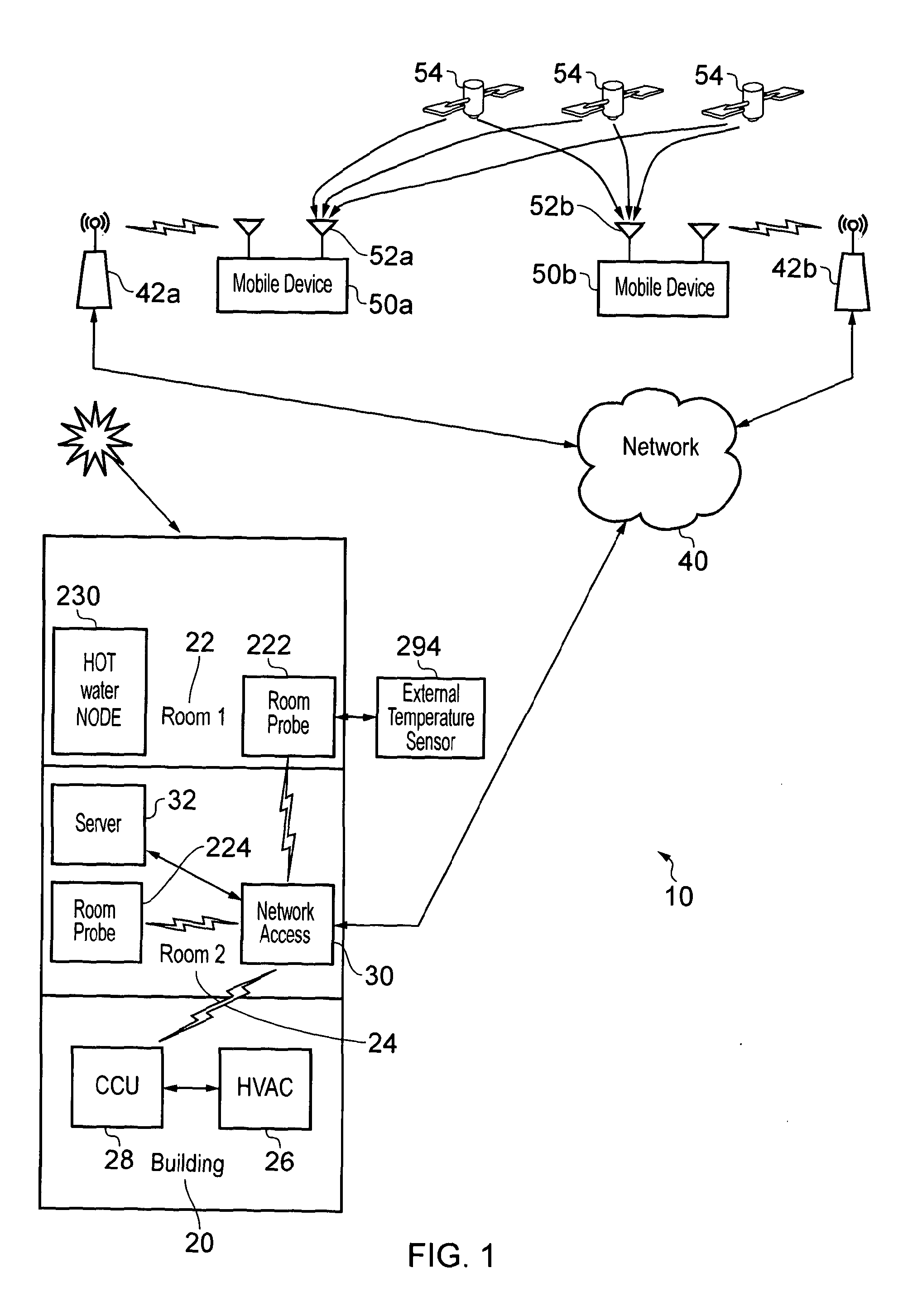
[0046]FIG. 1 is a schematic diagram of a system 10 according to the invention.

[0047]There is a building 20, which is connectable to one or more mobile devices 50a and 50b via a network 40.

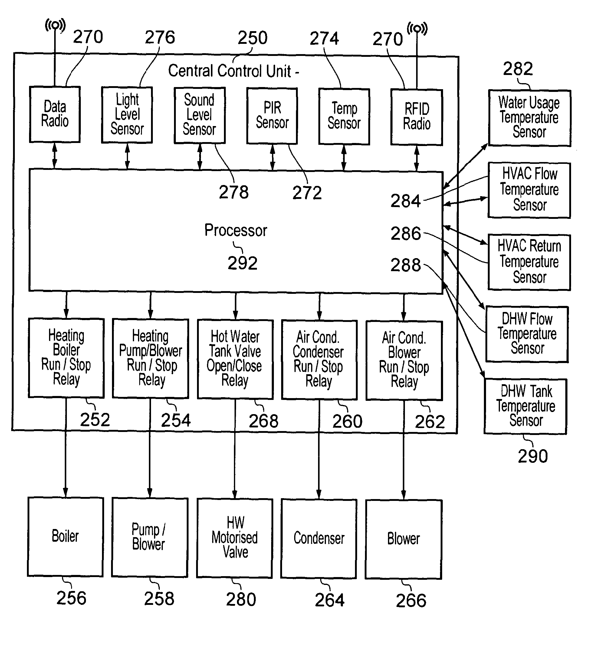
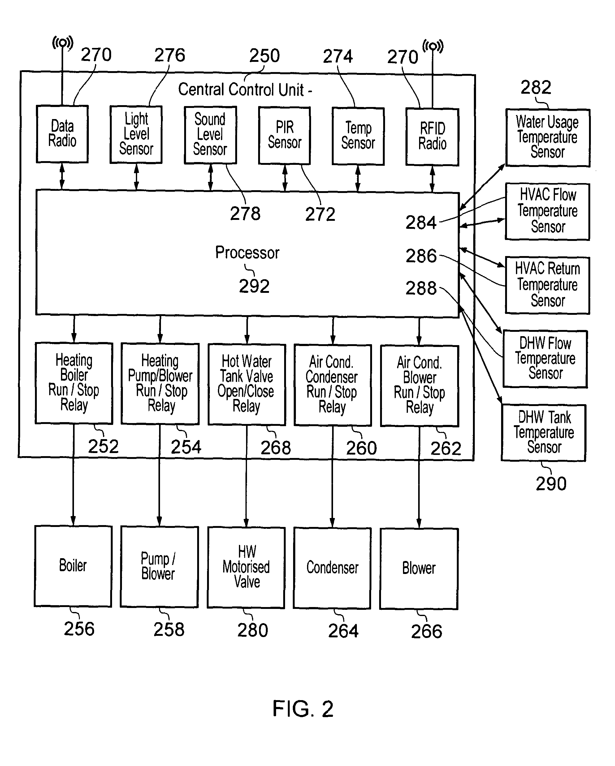
[0048]In this example, the building 20 has two rooms 22, 24 each having a room probe 222, 224 respectively which is capable of monitoring a number of things such as temperature and occupancy for example. One of the room probes 222 is in communication with an external temperature sensor 294. Room one 22 additionally includes a hot water tank and the hot water node 230. The building 20 also houses a HVAC 26 which is controlled by a CCU (central control unit) 28 and a network access point 30 which, in this example is connected to a server 32 which includes a data store or database and wirelessly connected to the room probes 22, 24 and the CCU 28.

[0049]The network access 30 can access a network or internet 40 which links to one or more mobile devices 50a, 50b via any of a number of receiver / transmitter...


PUM


Abstract

An HVAC control system is described comprising: a server (32) having planned information, a man-machine interface (50) capable of communication with the server (32) to provide dynamic information about building occupancy based on a change in cold water in a mains riser. A central control unit (28) which can communicate with the server (32), and a room node (22, 24) for providing information about conditions within the room whereby, the information about room conditions is compared to planned information and / or dynamic information and adjustments made accordingly. The room node (22, 24) may comprise sensors (276, 278, 272, 274) which provide information about conditions in the room. Dynamic information can include changes to planned occupancy, the effect of solar heating and weather conditions. Changes to planned occupancy can be established through detecting location (internally or externally) or destination of a user; and calculating estimated time of arrival of a user.

Description

FIELD OF THE INVENTION[0001]This invention relates to a control system, more particularly the invention relates to an improved control system for use in heating, ventilation and air conditioning (HVAC) systems.BACKGROUND OF THE INVENTION[0002]Many domestic heating boilers installed in the UK (circa 22 million), including most of the so-called “energy-efficient condensing boilers” not operate at optimal efficiency for only a relatively small amount of the time they are operational. These incumbent systems generally rely upon human intervention in programming a panel that normally works on a seven-day cycle with typically three on / off events throughout each day. This somewhat rigid approach does not adequately take into consideration the dynamic changes of a typical family lifestyle which affects usage of the building. As a consequence such repetitive programmes are wasteful and very efficient.[0003]Domestic heating CO2 emissions are said to represent one quarter of all UK CO2 emissio...

Claims


Application Information

Patent Timeline
Patent Type & Authority Applications(United States)
IPC IPC(8): G05B13/02
CPCF24F11/0034F24F2011/0013F24F2011/0061G05B2219/2642G05B13/02G05B15/02G05D23/1927F24F11/30F24F2110/12F24F2120/10F24F11/63F24F11/46F24F11/64
Inventor KNAPTON, CARYCOLLINS, PAULWEBB, BARRY
Owner TELEPURE
Learn More