
Centrifugal compressor

a centrifugal compressor and compressor technology, applied in the direction of machines/engines, stators, liquid fuel engines, etc., can solve the problems of high pressure loss, damage to efficiency, and expensive finishing, and achieve the effect of reducing production expenditure and high pressure loss

Inactive Publication Date: 2013-03-14
SIEMENS AG
View PDF8 Cites 7 Cited by
  • Summary
  • Abstract
  • Description
  • Claims
  • Application Information

AI Technical Summary

Benefits of technology

The invention aims to improve the centrifugal compressor by reducing production expenditure and avoiding high pressure losses in the collector helix. The use of a single-piece collector helix design eliminates deposition and flow contour distortion caused by part joints, reducing the need for expensive finishing processes. Additionally, the helix serves as support for a shaft bearing and carries a shaft seal, resulting in a compact design and a short tolerance chain between the impellers and the housing, and achieving low seal clearances or laxity.

Problems solved by technology

Said expensive geometry is due to the fact that unfavorable flow contours, which generate high pressure losses in the collector chamber, are also particularly damaging for the efficiency as a result of the increased density of said fluid.
In the case of conventional compressors, the collector helix, just as the housing, has a horizontal part joint which either generates an unfavorable deposition in the flow contour of the collector helix, which leads to pressure losses, or requires expensive finishing which has to be carried out in a time-intensive, individualized manner on the element which is realized, as a rule, as a cast part.

Method used


Image

  • Centrifugal compressor
  • Centrifugal compressor

Examples


Embodiment Construction

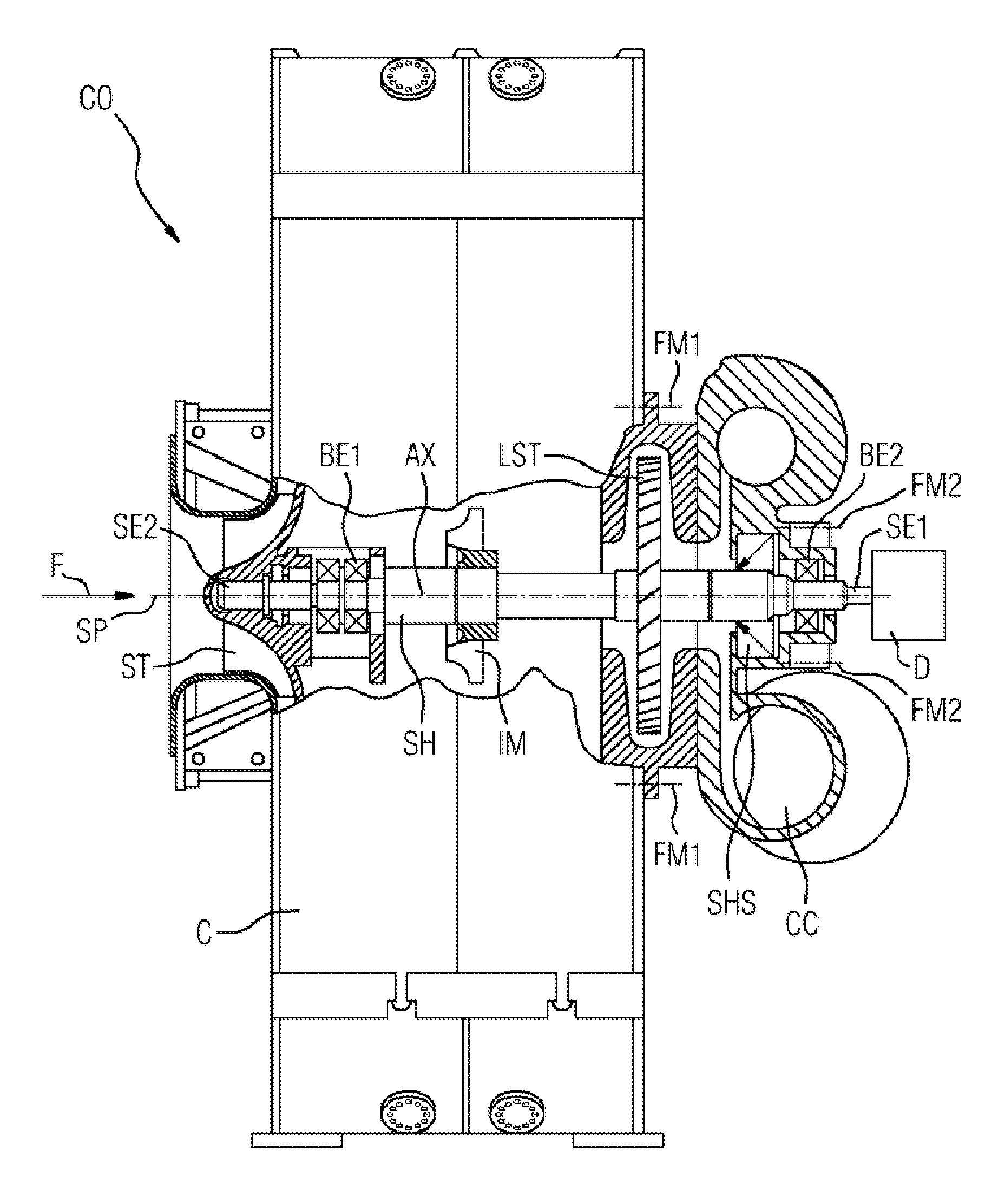
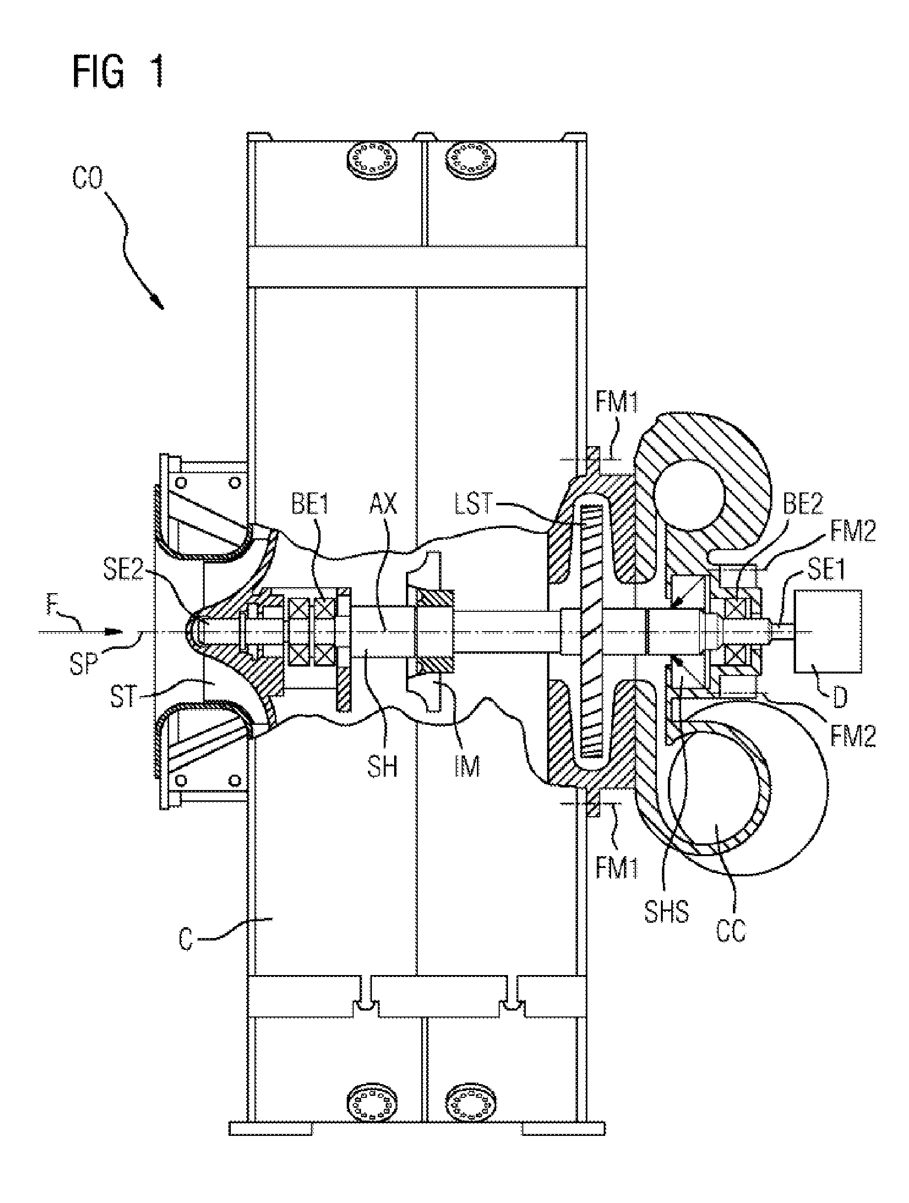
[0016]FIG. 1 shows a schematic longitudinal section through a compressor CO as claimed in the invention. Essential component parts of the compressor CO are a housing C, a shaft SH, the impellers IM—only one of which is shown and supports an overhang stage ST, a collector helix CC which is flanged to the housing C and a drive D which rotates the shaft SH.

[0017]The shaft SH extends along a machine axis AX which is at the same time the axis of rotation of the drive D. A process fluid F is sucked in axially by the compressor CO and enters into an overhang stage ST, continues to be compressed downstream by means of the impellers IM and enters into a last stage LST in order to be collected finally in the collector helix CC for entry into the machine module downstream. The shaft SH is mounted in two radial bearings BE1, BE2. The shaft SH has a first shaft end SE1 and a second shaft end SE2, the first shaft end SE1 being driven by the drive D and the second shaft end SE2 carrying the overha...


PUM


Abstract

A centrifugal compressor includes a housing having a part joint plane which extends parallel to or along a machine axis, and a shaft extending along the machine axis and having a first shaft end and a second shaft end. At least one impeller is mounted on the shaft. A collector helix is arranged downstream of the at least one impeller and collects the compressed fluid prior to an outflow into a following machine module. The collector helix is arranged on the first shaft end. A drive is arranged on the first shaft end. An axial intake at an overhang stage of the centrifugal compressor is provided on the shaft on the second shaft end. The collector helix is realized as a single piece in the circumferential direction and is flanged to the housing of the centrifugal compressor.

Description

CROSS REFERENCE TO RELATED APPLICATIONS[0001]This application is the U.S. National Stage of International Application No. PCT / EP2011 / 057660, filed May 12, 2011 and claims the benefit thereof. The International Application claims the benefits of German application No. 10 2010 020 891.4 DE filed May 18, 2010. All of the applications are incorporated by reference herein in their entirety.FIELD OF INVENTION[0002]The invention relates to a centrifugal compressor having a shaft which extends along a machine axis, there being a drive on the side of a collector helix, which collects a compressed fluid downstream of at least one impeller upstream of an outflow into a following machine module, which drive is arranged on a shaft end which is guided out of a housing of the centrifugal compressor, wherein an axial intake is provided on an overhang stage of the centrifugal compressor on an opposite shaft end of the shaft.BACKGROUND OF INVENTION[0003]These types of compressors are used in particul...

Claims


Application Information

Patent Timeline
Patent Type & Authority Applications(United States)
IPC IPC(8): F01D1/02
CPCF04D17/122F04D29/441F04D29/4206F04D29/083
Inventor GEISNER, JURGEN
Owner SIEMENS AG
Learn More