Eureka AIR delivers breakthrough ideas for toughest innovation challenges, trusted by R&D personnel around the world.

Epitaxial wafer susceptor and supportive and rotational connection apparatus matching the susceptor

a technology of supporting and rotational connection and susceptor, which is applied in the direction of chemically reactive gases, coatings, crystal growth processes, etc., can solve the problems of large rotational inertia, increased surface treatment difficulty, and difficult to regulate the levelness and dynamic balance of the susceptor, so as to reduce the production cost of epitaxial wafers, avoid component wear caused by friction transmission, and reduce the effect of high-speed reliability

Inactive Publication Date: 2013-03-14
JIANGSU ZHONGSHENG SEMICON EQUIP
View PDF9 Cites 14 Cited by
  • Summary
  • Abstract
  • Description
  • Claims
  • Application Information

AI Technical Summary

Benefits of technology

The present invention relates to an epitaxial wafer susceptor that can be mechanically loaded and unloaded, and connected to a driving shaft through a susceptor rotating shaft. The susceptor rotating shaft has a downward-protruding structure, which allows for easy surface treatment and guarantees mechanical strength at the center of the susceptor without increasing its overall thickness, reducing material consumption, weight, and thermal capacity. This results in improved production efficiency and capability of temperature regulation and control for epitaxial reaction. Additionally, positioning grooves and positioning keys are set on the sides of the susceptor rotating shaft and the counter bore of the driving shaft to synchronize their rotation speeds, reducing friction transmission and improving reliability and long-term use under high-speed and medium-speed rotation conditions. This also reduces wear and tear and reduces the need for susceptor substitutes, reducing production costs.

Problems solved by technology

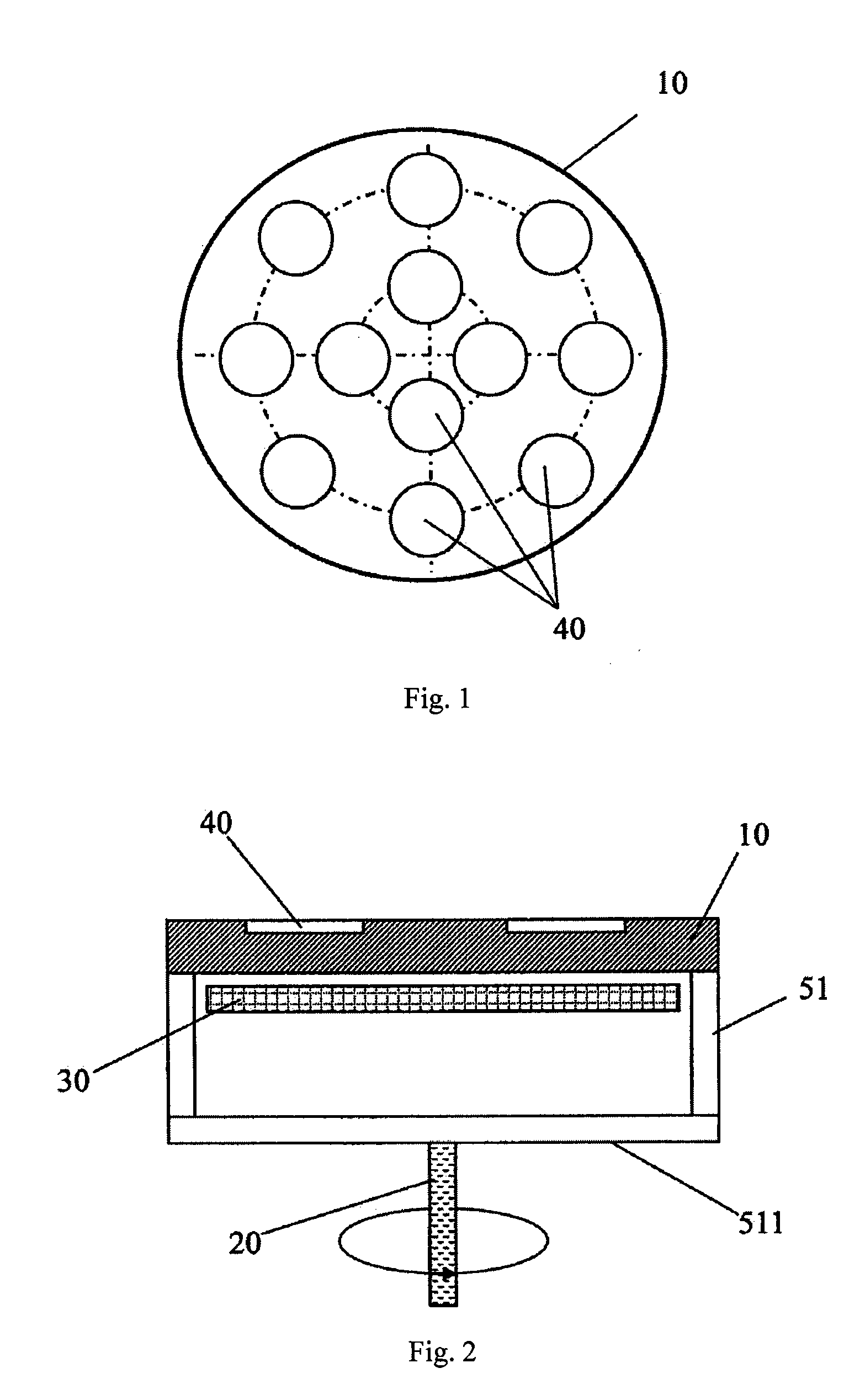
Therefore, it is difficult to regulate the levelness and dynamic balance of the susceptor 10.
Moreover, the rotational inertia is large because of the large number of components.
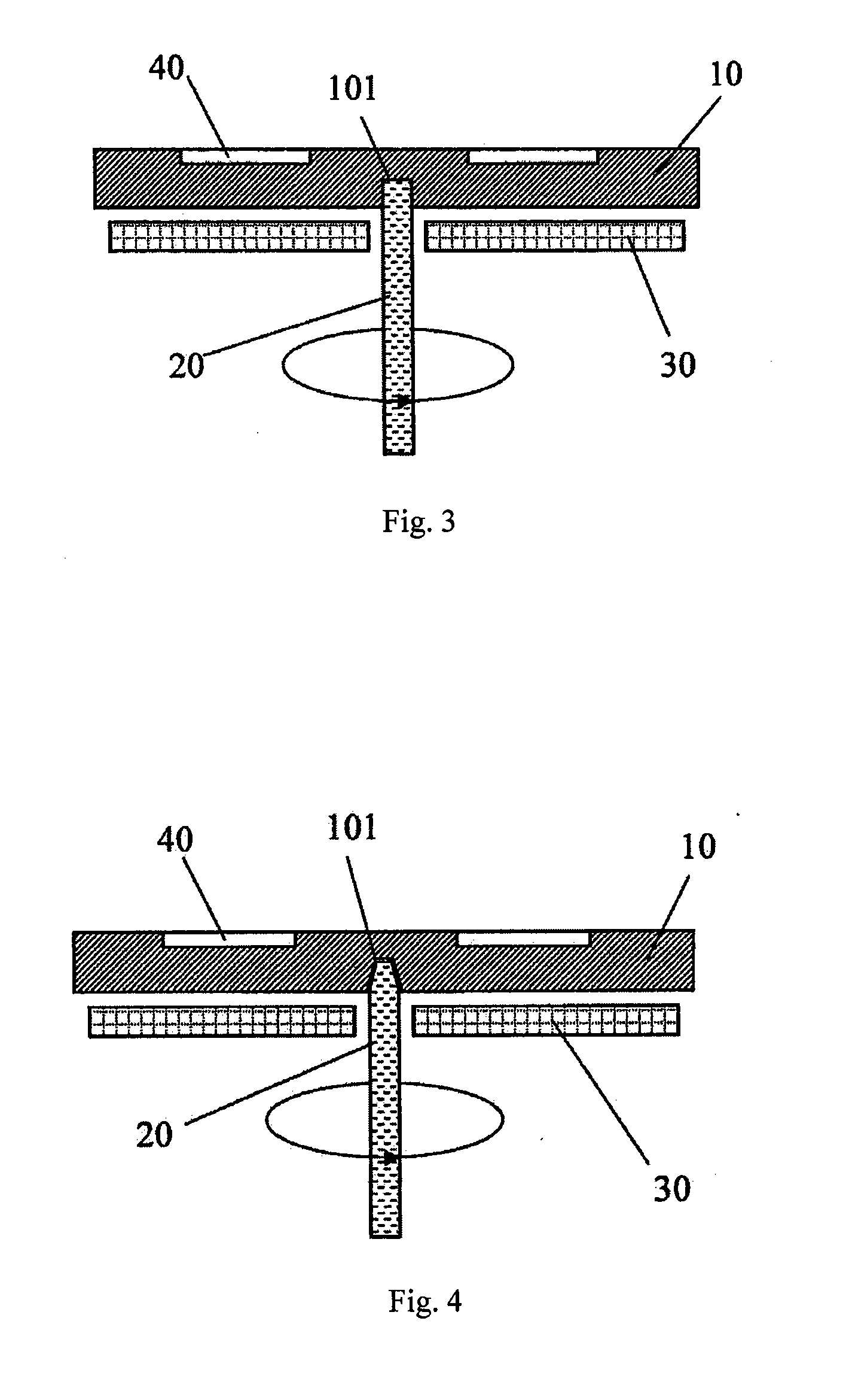
However, because the contact surface is within the counter bore 101, the difficulty of surface treatment is increased.

Method used


Image

  • Epitaxial wafer susceptor and supportive and rotational connection apparatus matching the susceptor
  • Epitaxial wafer susceptor and supportive and rotational connection apparatus matching the susceptor
  • Epitaxial wafer susceptor and supportive and rotational connection apparatus matching the susceptor

Examples


embodiment 1

[0056]As shown in FIG. 5 or FIG. 6, in this embodiment, the susceptor rotating shaft 100 under the center location of the bottom of the susceptor 10 is in the form of a downward-protruding step, comprising a first boss 110 in the form of a cylinder provided on the bottom of the susceptor 10 and a second boss 120 in the form of a cylinder (FIG. 5) or a cone (FIG. 6) provided below the first boss 110 with a smaller diameter. The annular end face 111 of the first boss 110 is parallel to both the top surface 11 and the bottom surface 12 of the susceptor 10.

[0057]A counter bore 200 is set inside an upper end of the driving shaft 20, and the annular top surface 211 of the counter bore 200 is perpendicular to the axis of the driving shaft 20. When the susceptor 10 is placed into the reaction chamber 50, the second boss 120 of the susceptor rotating shaft 100 is completely inserted into the counter bore 200. The side 112 of the second boss 120 guides the susceptor 10 in the vertical directi...

embodiment 2

[0059]As shown in FIG. 7, in this embodiment, the susceptor rotating shaft 100 at the center location on the bottom of the susceptor 10 is a cylindrical or conic (not shown in the figure) step protruding downward, and the end face 121 of the step is parallel to both the top surface 11 and the bottom surface 12 of the susceptor 10.

[0060]The susceptor rotating shaft 100 is positioned in a plane via its side 122 of the step. When the susceptor rotating shaft 100 is inserted into the counter bore 200 set inside an upper end of the driving shaft 20, the end face 121 of the step is located on the bottom surface 222 of the counter bore 200, so that the susceptor 10 is positioned in the reaction chamber 50 in vertical direction, and that the susceptor 10 is supported by the driving shaft 20. The effective area supporting the susceptor 10 of the bottom surface 222 of the counter bore 200 of the driving shaft 20 is determined by the diameter of the susceptor rotating shaft 100.

[0061]When the ...

embodiment 3

[0062]The structure of embodiment 3 is different from the structure according to the above embodiments 1 and 2 in which the susceptor 10 is driven to rotate with the driving shaft 20 mainly via the matching between a pair of contact surfaces on the susceptor rotating shaft 100 and the driving shaft 20, which are parallel to the top surface 11 and the bottom surface 2 of the susceptor 10.

[0063]As shown in FIG. 8, in this embodiment, the susceptor rotating shaft 100 is provided with a step protruding downward from the bottom surface 12 of the susceptor 10, which may be cylindrical or conic; and correspondingly, the counter bore 200 inside the upper end of the driving shaft 20 is set as cylindrical or conic or other forms matching the susceptor rotating shaft 100, so that after the susceptor rotating shaft 100 is inserted into the counter bore 200, the side 131 of the step of the susceptor rotating shaft 100 comes into contact with the side 231 of the counter bore 200 of the driving sh...


PUM

PropertyMeasurementUnit
Diameteraaaaaaaaaa

Abstract

Disclosed is an epitaxial wafer susceptor and a supportive and rotational connection apparatus matching the susceptor used for an MOCVD reaction chamber. The susceptor comprises a top surface and a susceptor rotating shaft protruding downward. A vertical driving shaft is coupled to the susceptor. The driving shaft comprises a counter bore inside an upper end of the driving shaft. At least a part of the susceptor rotating shaft is inserted into the counter bore if the susceptor is loaded. The susceptor is positioned and supported in the reaction chamber via coupling and connection between a contact surface of the susceptor rotating shaft and a corresponding contact surface of the counter bore. The susceptor is driven to rotate by the driving shaft if the driving shaft rotates. Reactant gases are introduced into the reaction chamber for an epitaxial reaction or a film deposition on the epitaxial wafers placed on the susceptor.

Description

[0001]The present application is a continuation of PCT application PCT / CN2011 / 001147, filed on Jul. 12, 2011, titled “EPITAXIAL WAFER SUSCEPTOR AND SUPPORTIVE AND ROTATIONAL CONNECTION APPARATUS MATCHING THE SUSCEPTOR”, which claims the priority of Chinese Application No. 201010263418.3 filed on Aug. 19, 2010, titled “EPITAXIAL WAFER SUSCEPTOR AND SUPPORTIVE AND ROTATIONAL CONNECTION APPARATUS MATCHING THE SUSCEPTOR”, which is incorporated herein by reference in its entirety.FIELD OF THE INVENTION[0002]The present invention relates to an epitaxial wafer susceptor placed and removed via a robotic arm in a metal organic chemical vapour deposition (MOCVD) system for producing compound semiconductor photoelectric devices, and a connection apparatus matching the susceptor for supporting the susceptor at the center and driving the susceptor to rotate.BACKGROUND OF THE INVENTION[0003]Metal organic chemical vapour deposition system (hereinafter referred to as MOCVD system) is an equipment f...

Claims


Application Information

Patent Timeline
IPC IPC(8): C23C16/458
CPCC23C16/4584C23C16/4585C30B25/12H01L21/68792H01L21/68764H01L21/68771H01L21/67754
Inventor JIN, XIAOLIANGCHEN, AIHUASUN, RENJUNZHANG, WEI
Owner JIANGSU ZHONGSHENG SEMICON EQUIP
Why Eureka
Eureka Blog
Learn More