Apparatus for the exact reconstruction of the object wave in off-axis digital holography

a technology of object wave and exact reconstruction, applied in the field of amplitude and quantitative phase imaging using digital holography, can solve the problems of insufficient dc terms from the hologram, limited methods, and insufficient in most cases

Active Publication Date: 2013-03-07
MITUTOYO CORP
View PDF1 Cites 13 Cited by
  • Summary
  • Abstract
  • Description
  • Claims
  • Application Information

AI Technical Summary

Benefits of technology

[0042]Here a preferred embodiment provides a method for reconstructing the image of an object represented by a digital hologram as obtained a method referred to above, wherein the digital hologram is subjected to a digital representation of a plane wave as a reference wave and that the reconstruction is executed digitally.
[0043]Yet another embodiment provides such a method, wherein the image representing the object is digitally processed to obtain a digital height map.
[0044]The present invention can also be applied in optical coherence tomography. According to a corresponding method the measurement beam is adapted to penetrate the object at least partially and to generate scattered beams in the object, and wherein the scattered beams are combined with both the first and the second measurement beams to form an interference pattern on

Problems solved by technology

However, this method is limited by the available number of pixels in the CCD camera or optical sensor.
It's a simple way to reduce the DC terms from the hologram but it's not sufficient in most of cases.
If the object wave intensity is not constant in hologram plane in general, for example, the DC term caused by the object wave cannot be eliminated with this method.
However, they are also limited by these two aspects; one is that a certain fraction of the spectrum can be availabl

Method used


Image

  • Apparatus for the exact reconstruction of the object wave in off-axis digital holography
  • Apparatus for the exact reconstruction of the object wave in off-axis digital holography
  • Apparatus for the exact reconstruction of the object wave in off-axis digital holography

Examples


Embodiment Construction

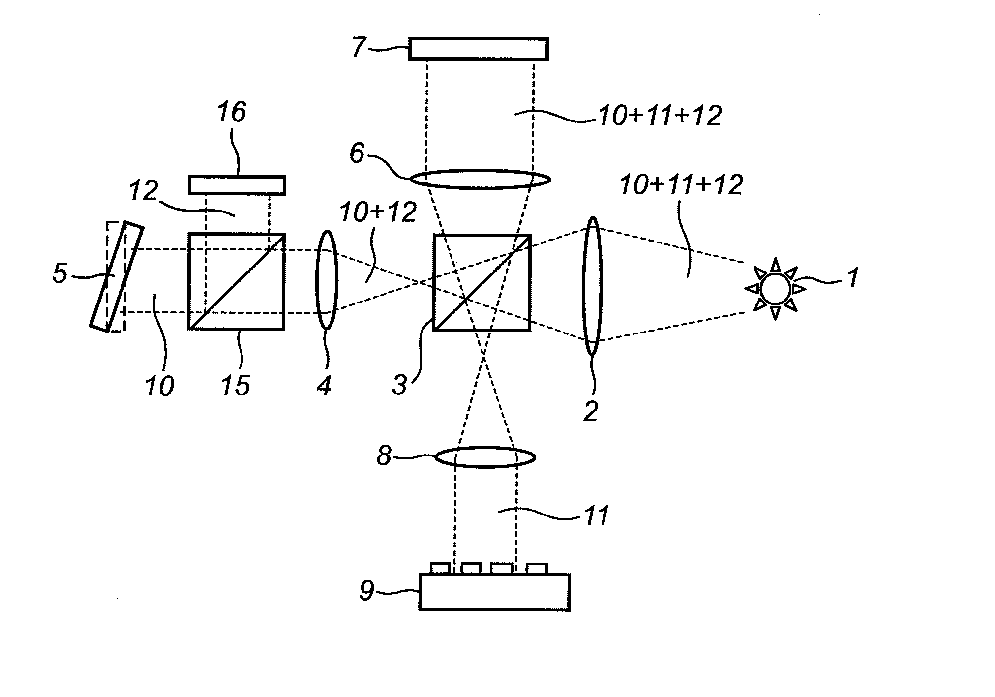
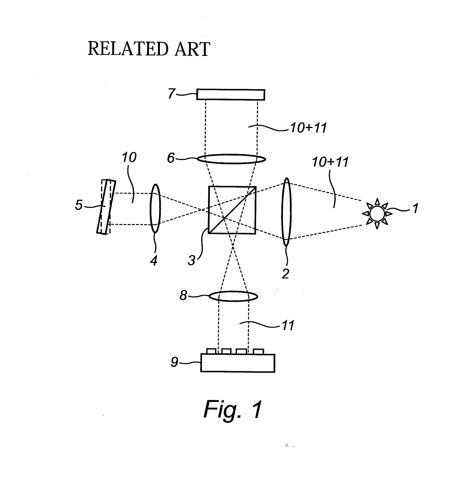
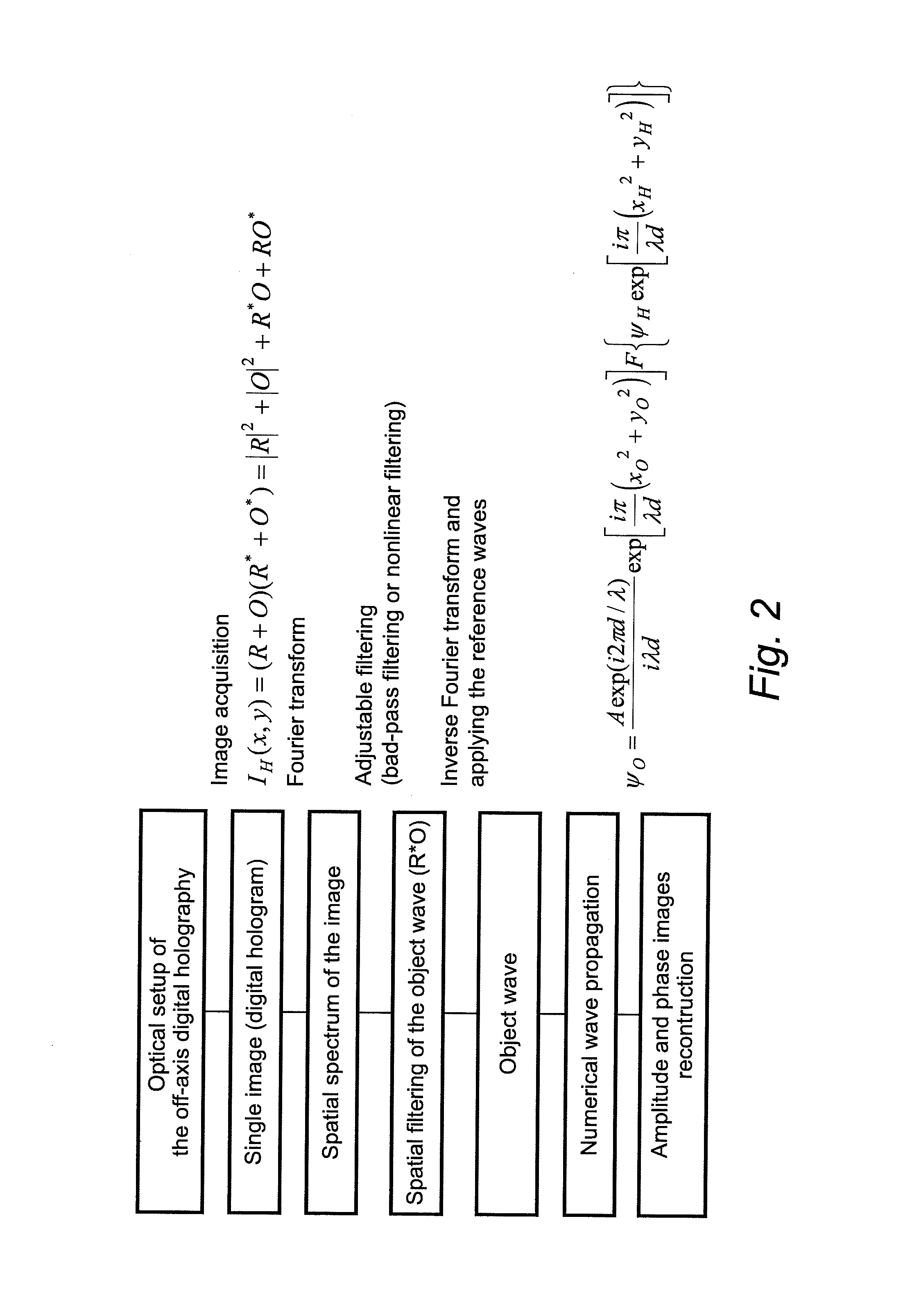
[0066]FIG. 1 discloses a typical prior art configuration for off-axis digital holography, wherein the hologram is obtained from the interference between a coherent object wave (O) and a coherent reference wave (R). Then, the two-dimensional (2D) intensity distribution (IH) can be expressed as:

IH(x,y)=(R+O)(R*+O*)=|R|2+|O|2+R*O+RO*  (1)

wherein R* and O* denote the complex conjugates of the both waves.

[0067]After recording the hologram, the reconstructed wave (ψ) can be obtained by the illumination of the hologram with a reconstruction wave U as follows:

ψ=IH·U=|R|2U+|O|2U+R*OU+RO*U  (2)

[0068]The first two terms of Eq. (2) form the zero-order of diffraction, sometimes called a DC term. The third and the fourth terms are produced by the interference terms and they generate two conjugate or twin images of the object. The third term (R*OU) produces a virtual image located at the initial position of the object (object plane) and the fourth term (RO*U) produces a real image located on the o...


PUM


Abstract

A method for preparing a digital hologram representing an image of an object, which includes generating a measurement beam and a first reference beam, irradiating the object by the measurement beam and guiding the measurement beam reflected to an optical sensor. The method also includes guiding the first reference beam to a first mirror, extending under an angle different from 90° with the optical axis of the first reference beam, and guiding the reflected beam to the optical sensor so that both beams generate an interference pattern on the sensor. The method further includes reading out the sensor and providing a digital signal representing the interference pattern on the optical sensor, and processing the signal to obtain a digital hologram.

Description

INCORPORATION BY REFERENCE[0001]This application is based upon and claims the benefit of priority from European patent application No. 11179946.6, filed on Sep. 2, 2011, the disclosure of which is incorporated herein in its entirety by reference.BACKGROUND OF THE INVENTION[0002]1. Field of the Invention[0003]This invention is related to the amplitude and quantitative phase imaging using digital holography of digital holographic microscopy for real time 3D measurements.[0004]2. Description of Related Art[0005]Digital holography is an effective tool to record not only the amplitude image but also the phase image contrary to the normal imaging techniques. The main advantage of digital holography is obviously originated from the real time 3D measurements of the target with only a single image. In addition, digital holography allows reconstruction of the amplitude and phase of the object wave even though the specimen is not in the best focus or the optical system includes aberrations.[00...

Claims


Application Information

Patent Timeline
IPC IPC(8): G03H1/16
CPCG03H1/0866G03H1/265G03H1/28G03H2001/0454G03H2001/0456G03H2001/0825G06E3/003G03H2222/24G03H2223/26G03H1/0443G03H1/10G03H1/16G03H2001/0883G03H2001/0452G01B9/02028G01B9/02091G01B9/02032G01B9/02047
Inventor JOO, KI-NAM
Owner MITUTOYO CORP
Why Eureka
Try Eureka