
Motor and manufacturing method thereof and fan

a manufacturing method and motor technology, applied in the direction of lamination, lamination apparatus, chemical apparatus and processes, etc., can solve the problems of vibration accompanying noise, and achieve the effects of reducing material cost, reducing vibration transmission, and simplifying the manufacturing process

Active Publication Date: 2013-03-07
DELTA ELECTRONICS INC
View PDF9 Cites 0 Cited by
  • Summary
  • Abstract
  • Description
  • Claims
  • Application Information

AI Technical Summary

Benefits of technology

The invention provides a motor and fan that can reduce vibration, simplify assembly, and increase production efficiency. It achieves this by reducing vibration transmission between the substrate and bushing, and providing a buffer between them. This is achieved by connecting the substrate and bushing with a cushioning material that can be easily molded in place, eliminating the need for additional assembly elements and reducing material costs.

Problems solved by technology

Besides, the noise is produced accompanying with the vibration.

Method used


Image

  • Motor and manufacturing method thereof and fan
  • Motor and manufacturing method thereof and fan
  • Motor and manufacturing method thereof and fan

Examples


Embodiment Construction

[0038]The present invention will be apparent from the following detailed description, which proceeds with reference to the accompanying drawings, wherein the same references relate to the same elements.

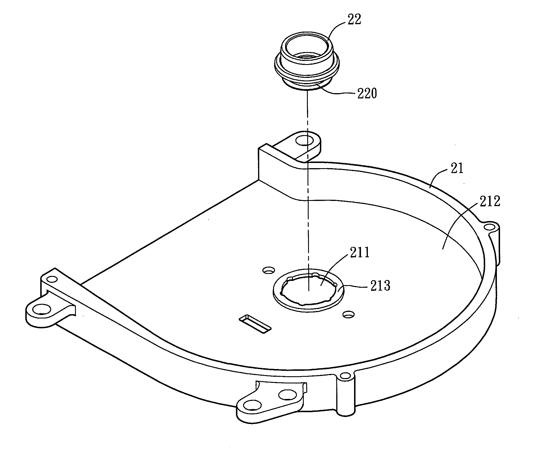
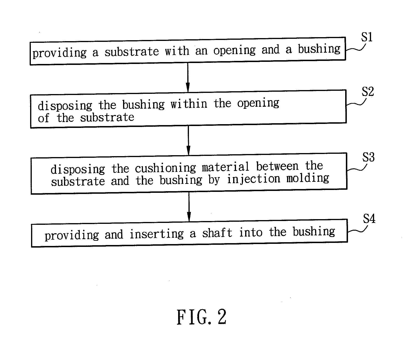
[0039]FIG. 2 is a flow chart of a manufacturing method for a motor according to a preferred embodiment of the present invention, FIG. 3 is a schematic diagram showing a motor in manufacturing process according to the present invention, and FIG. 4 is a sectional diagram showing a motor in manufacturing process according to the present invention. In this embodiment, a motor 2 can be applied to, for example but not limited to, the fan or the likes.

[0040]First, referring to FIGS. 2 to 4, the step S1 is to provide a substrate 21 with an opening 211 and a bushing 22. The substrate 21 in this embodiment comprises a bottom portion 212 and a protruding portion 213. The protruding portion 213 is protruding from the bottom portion 212 and extending toward the bushing 22. In this case, the bottom...


PUM

PropertyMeasurementUnit
elasticaaaaaaaaaa
strengthaaaaaaaaaa
sizeaaaaaaaaaa

Abstract

A method for manufacturing a motor includes the following steps of: providing a substrate with an opening and a bushing; disposing the bushing within the opening of the substrate; providing a cushioning material disposed between the substrate and the bushing by injection molding.

Description

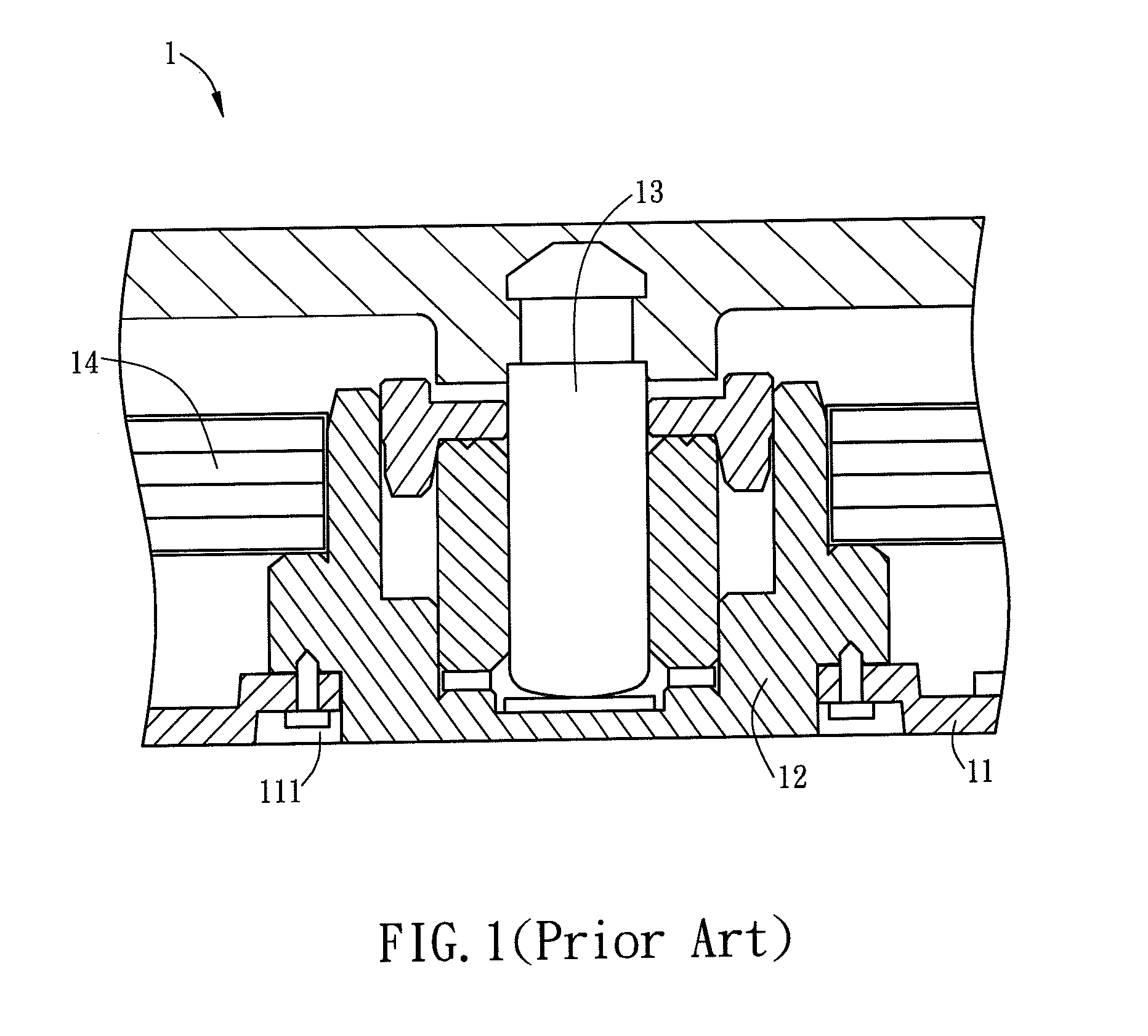
CROSS REFERENCE TO RELATED APPLICATIONS[0001]This Non-provisional application claims priority under 35 U.S.C. §119(a) on Patent Application No(s). 100131621 filed in Taiwan, Republic of China on Sep. 2, 2011, the entire contents of which are hereby incorporated by reference.BACKGROUND OF THE INVENTION[0002]1. Field of Invention[0003]The present invention relates to a motor, a method for manufacturing the motor and a fan.[0004]2. Related Art[0005]FIG. 1 is a schematic diagram showing a part of a conventional motor 1. The conventional motor 1 is an example of motor applied to a fan. The motor 1 includes a substrate 11, a bearing 12, a shaft 13 and a stator 14. The bearing 12 is disposed within an opening 111 of the substrate 11. The bearing 12 and the substrate 11 can be integrally formed. If the bearing 12 and the substrate 11 are separate components, they can be connected by injection molding or riveting (as shown in FIG. 1).[0006]When the fan rotates, the motor 1 also functions and...

Claims


Application Information

Patent Timeline
Patent Type & Authority Applications(United States)
IPC IPC(8): B29C45/14
CPCB29C45/14311B29C2045/1454B29C45/14467
Inventor LU, CHAO-WENCHAN, CHIH-WEI
Owner DELTA ELECTRONICS INC
Learn More