
Driving force transmission apparatus

a transmission apparatus and driving force technology, applied in the direction of mechanical actuated clutches, couplings, fluid couplings, etc., can solve the problems of adverse influence on the turning performance and fuel economy, and the inability to obtain desirable clutch action of the clutch, so as to reduce the drag torque and improve the response of the clutch action of the main clutch

Inactive Publication Date: 2013-03-07
JTEKT CORP
View PDF0 Cites 5 Cited by
  • Summary
  • Abstract
  • Description
  • Claims
  • Application Information

AI Technical Summary

Benefits of technology

The invention improves the performance of a driving force transmission system by reducing drag torque and enhancing the response of the main clutch.

Problems solved by technology

As a result, not only turning performance and fuel economy are adversely influenced but also desirable clutch action of the clutch is not obtained when the four-wheel-drive vehicle shifts from the two-wheel-drive mode to a four-wheel-drive mode.

Method used


Image

  • Driving force transmission apparatus
  • Driving force transmission apparatus
  • Driving force transmission apparatus

Examples


first embodiment

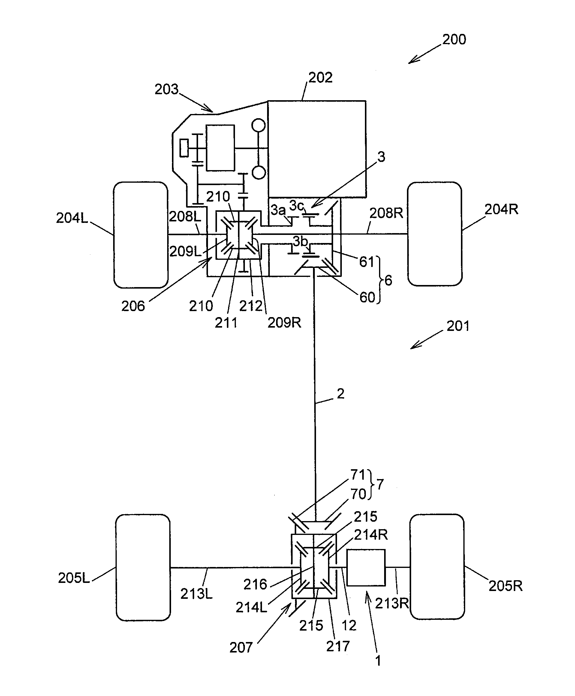
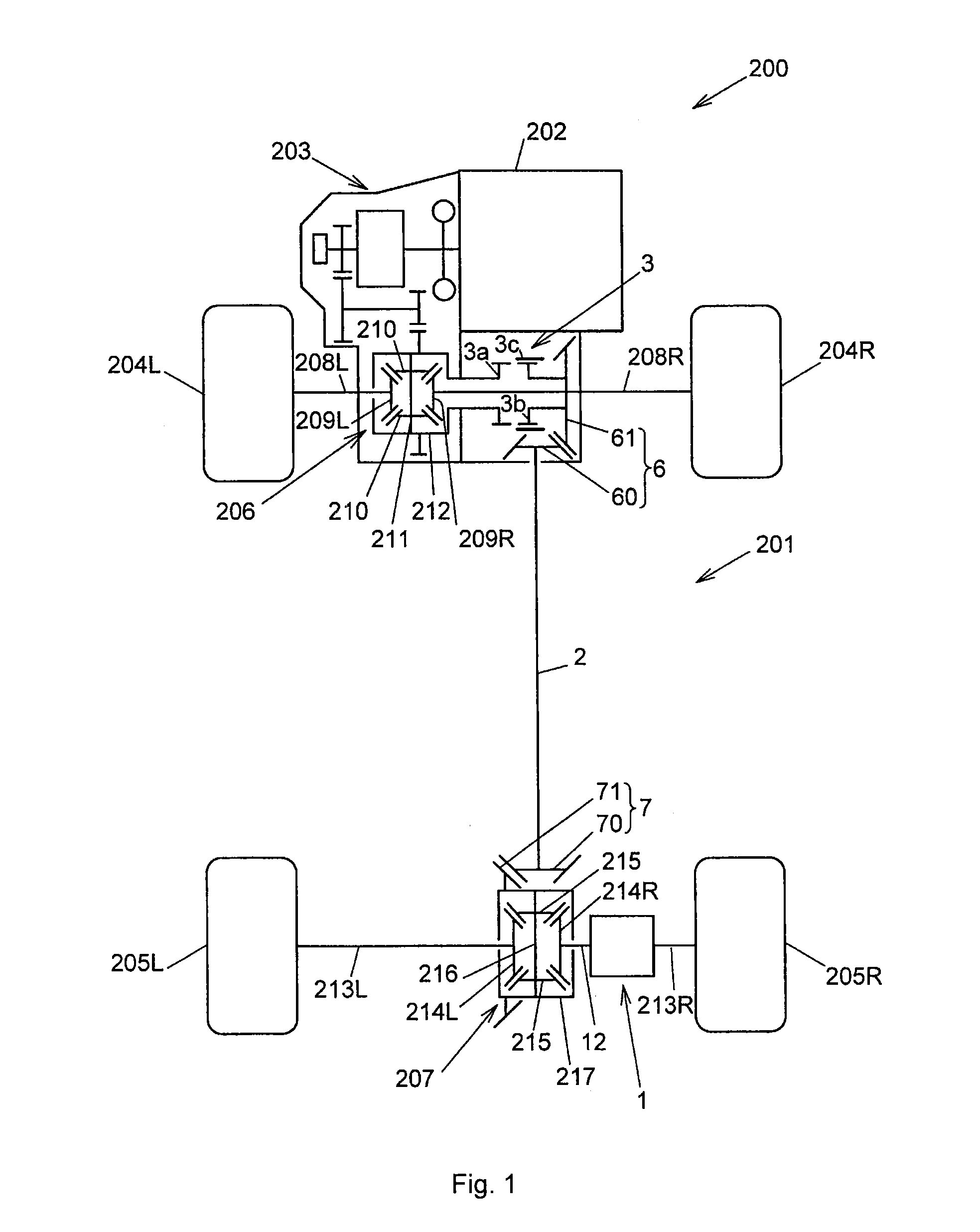
[0038]the invention will be described below. FIG. 1 schematically shows a four-wheel-drive vehicle 200. The four-wheel-drive vehicle 200 includes a driving force transmission system 201, an engine 202, a transmission 203, front wheels 204L, 204R that serve as main drive wheels, and rear wheels 205L, 205R that serve as auxiliary drive wheels.

[0039]The driving force transmission system 201 is arranged on a driving force transmission path that extends from the transmission 203 to the rear wheels 205L, 205R in the four-wheel-drive vehicle 200, together with a front differential 206 and a rear differential 207. The driving force transmission system 201 is mounted on a vehicle body (not shown) of the four-wheel-drive vehicle 200.

[0040]The driving force transmission system 201 includes a driving force transmission apparatus 1, a propeller shaft 2, and a driving force interrupting device 3. The driving force transmission system 201 is configured to be able to shift the four-wheel-drive vehi...

second embodiment

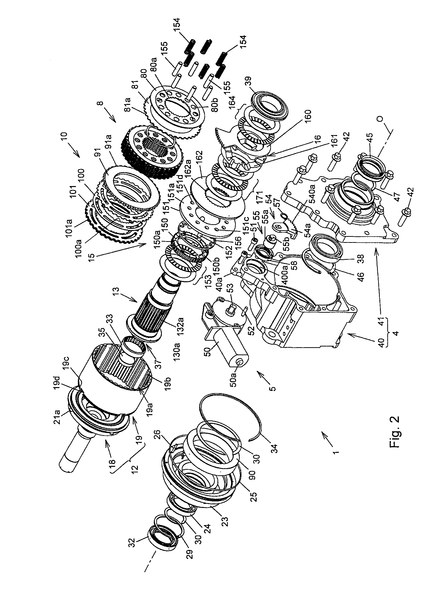
[0134]Next, a driving force transmission apparatus 190 according to the invention will be described with reference to FIG. 9 to FIG. 13 and FIG. 14A and FIG. 14B. FIG. 9 and FIG. 10 show the entirety of the driving force transmission apparatus. FIG. 11 shows a rear housing. FIG. 12 shows a first element of the rear housing. FIG. 13 shows a second element of the rear housing. FIG. 14A and FIG. 14B show a third element of the rear housing. In FIG. 9 to FIG. 13 and FIG. 14A and FIG. 14B, the components having functions the same as or equivalent to those in FIG. 2 and FIG. 3 are denoted by the same reference numerals as those in FIG. 2 and FIG. 3, and the detailed description thereof is omitted.

[0135]As shown in FIG. 9 and FIG. 10, the driving force transmission apparatus 190 according to the second embodiment of the invention differs from the driving force transmission apparatus 1 according to the first embodiment (shown in FIG. 3) where the rear housing 19 is of an open type so that t...


PUM


Abstract

A driving force transmission apparatus includes: a first cam mechanism that converts rotational force from a housing into first cam thrust force used as clutch force of a main clutch when the first cam mechanism is actuated through clutch action of a pilot clutch; and a second cam mechanism that is actuated prior to conversion of the rotational force into the first cam thrust force by the first cam mechanism, and that generates second cam thrust force for reducing an interval between clutch plates of the main clutch. The second cam mechanism includes an input cam member that rotates upon receiving rotational force used as actuating force of the input cam member from a cam actuating driving source, and an output cam member that generates the second cam thrust force between the output cam member and the input cam member and outputs the second cam thrust force.

Description

INCORPORATION BY REFERENCE / RELATED APPLICATION[0001]This application claims priority to Japanese Patent Applications No. 2011-190809 filed on Sep. 1, 2011 and No. 2011-256579 filed on Nov. 24, 2011 the disclosure of which, including the specification, drawings and abstract, is incorporated herein by reference in its entirety.BACKGROUND OF THE INVENTION[0002]1. Field of the Invention[0003]The invention relates to a driving force transmission apparatus.[0004]2. Discussion of Background[0005]Japanese Patent Application Publication No. 2003-014001 (JP 2003-014001 A) describes a conventional driving force transmission apparatus that is mounted in, for example, a four-wheel-drive vehicle, and in which a pair of rotary members are coupled to each other by a clutch so that torque is transmittable between the rotary members.[0006]The driving force transmission apparatus includes a first rotary member, a second rotary member, a friction main clutch, an electromagnetic clutch, a friction pilot...

Claims


Application Information

Patent Timeline
IPC IPC(8): F16D21/00
CPCF16D27/004F16D2500/5029F16D27/115F16D13/52F16D13/757F16D2023/123
Inventor FUJII, NORIYUKITAKUNO, HIROSHISUZUKI, KUNIHIKOTSUZUKI, YUJI
Owner JTEKT CORP
Learn More