Solar Reflection Apparatus

Inactive Publication Date: 2013-03-07
DOW CORNING CORP
View PDF26 Cites 16 Cited by
  • Summary
  • Abstract
  • Description
  • Claims
  • Application Information

AI Technical Summary

Benefits of technology

The invention is about a new apparatus for collecting solar energy. The main benefit of the new design is that it is easier and cheaper to build and install. It also allows for more accurate tracking of the sun, which increases efficiency. An auxiliary reflector is added to reflect solar energy that is not directly focused at the main reflector. This reflected energy is then directed back to the main collector, which is located at the axis of rotation. This improves the overall efficiency of the apparatus and reduces the cost of manufacture and installation.

Problems solved by technology

Mounting the reflection assembly at the focal axis, about which the assembly is rotated, significantly simplifies construction of the apparatus and hence the capital cost of manufacture and installation.

Method used


Image

  • Solar Reflection Apparatus
  • Solar Reflection Apparatus
  • Solar Reflection Apparatus

Examples


Embodiment Construction

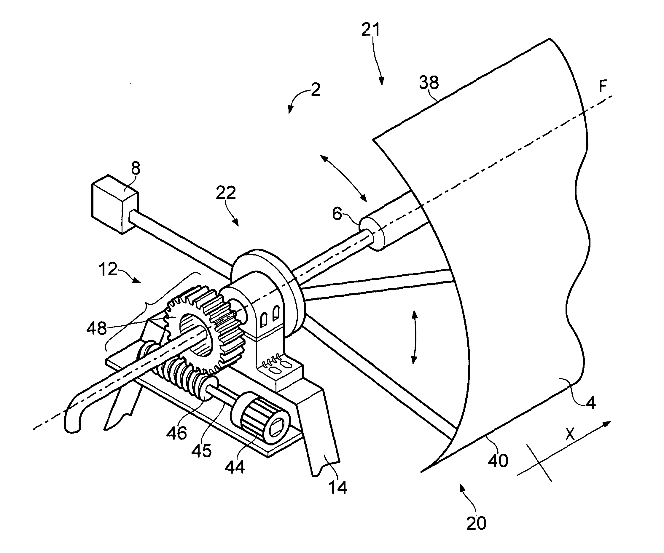
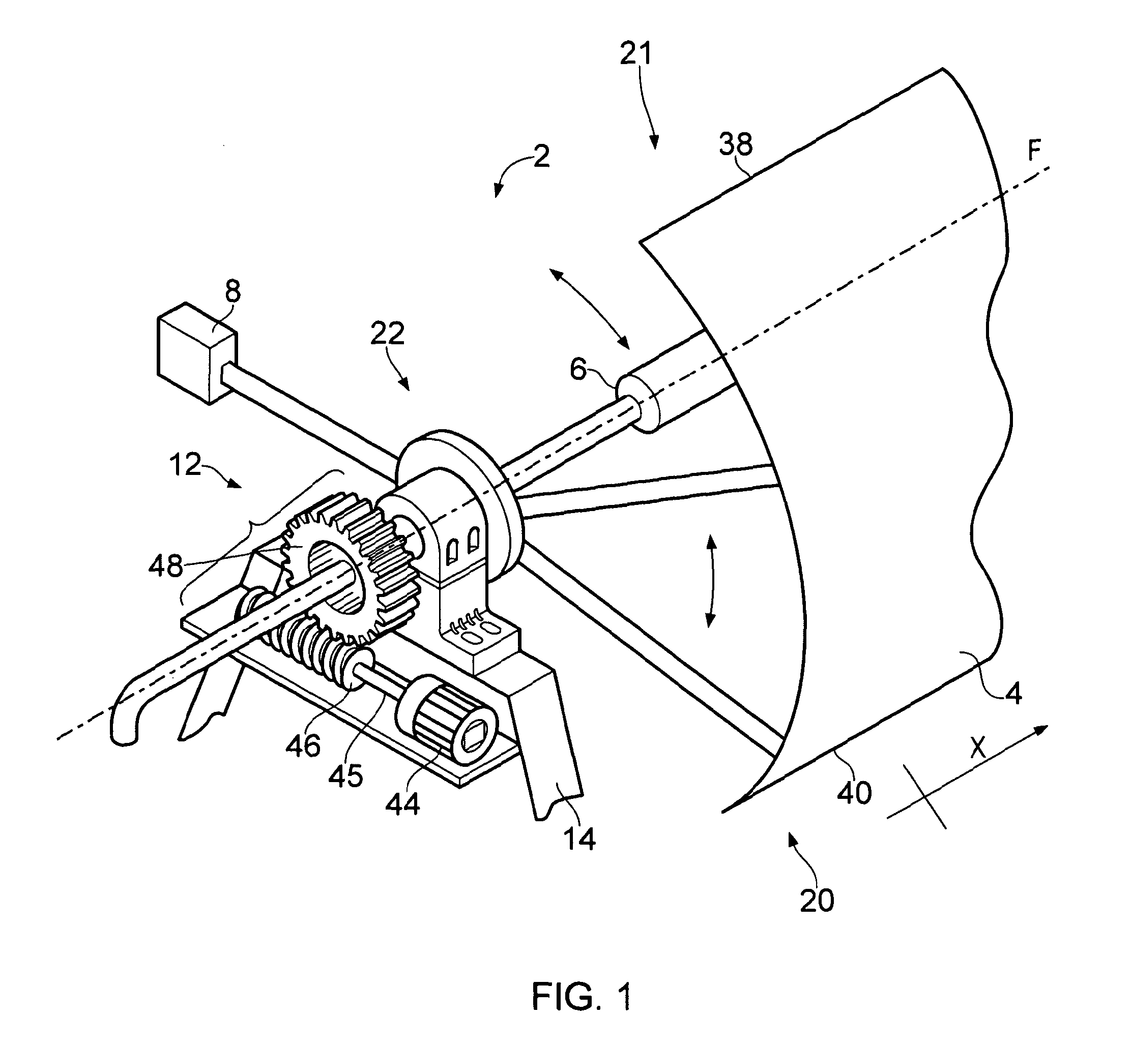
[0046]With reference to FIGS. 1 to 4, a solar collection apparatus 2 comprises a solar reflection apparatus 60 and a heat collecting element in the form of a collector pipe 6.

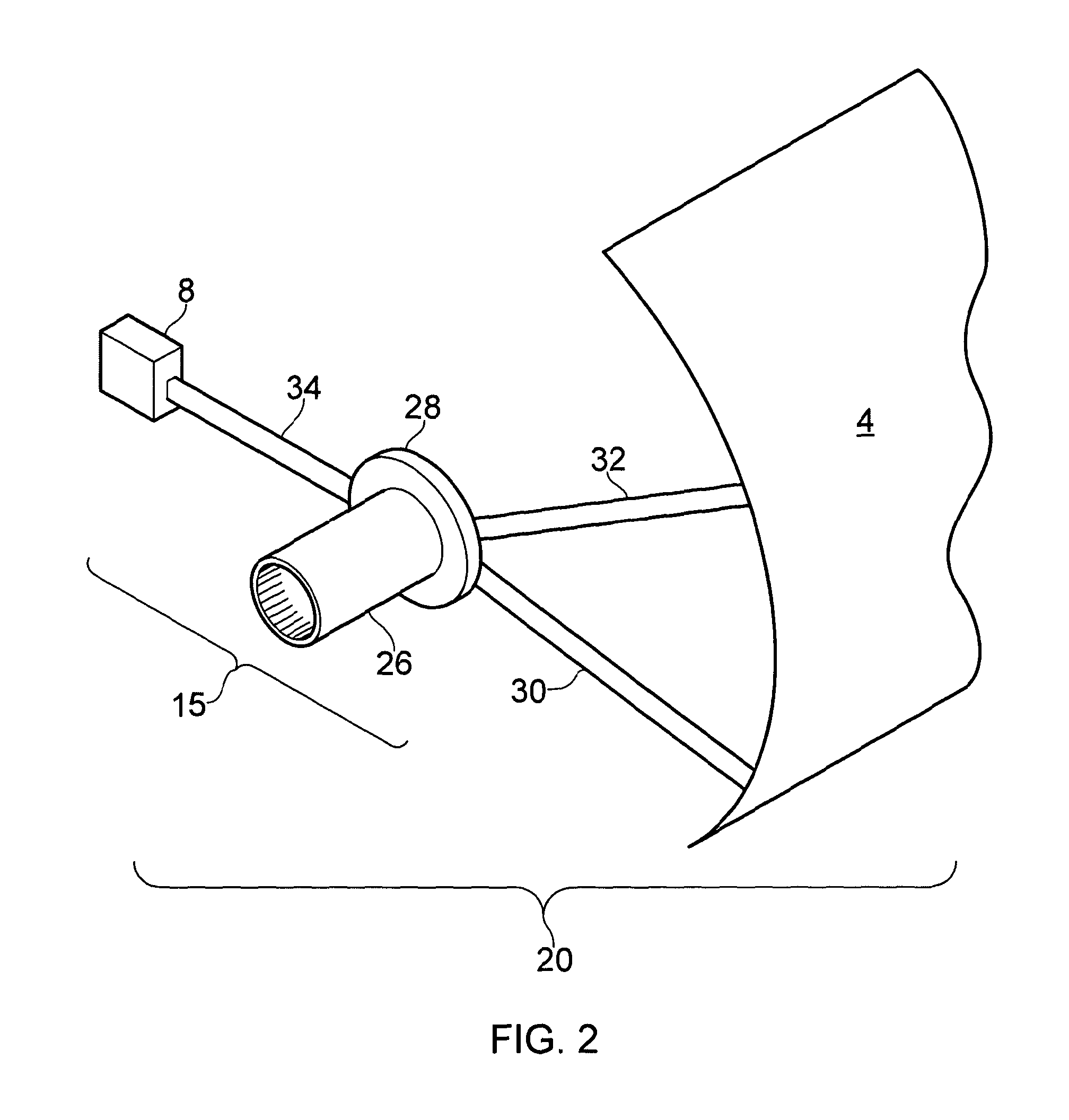
[0047]The solar reflection apparatus 60 (illustrated in FIG. 3) comprises a linear parabolic reflector 4, a counterweight 17 in the form of two counterweight units 8, 10 and a drive mechanism 12. The reflector 4 and counterweight units 8, 10 are connected via a support structure 15 in the form of two support units 22, 24 and together these elements constitute a solar reflection assembly 20 (illustrated in FIG. 2). The solar reflection assembly 20 is mounted for rotation about an axis of rotation, along which the collector pipe 6 extends.

[0048]The reflector 4 is a linear parabolic reflector, or parabolic trough, and extends linearly along an axis x from a first end 21 to a second end 23. The reflector 4 defines a focal axis F, onto which solar radiation approaching the reflector is focussed. The reflection assem...


PUM


Abstract

A solar reflection apparatus (60) is disclosed comprising a rotatable reflection (assembly 20) and a drive mechanism (12) which is operable to drive rotation of the reflection assembly (20) at its axis of rotation. The reflection assembly (20) comprises a curved linear reflector (4) defining a focal axis F, a counter weight (17) operable to balance the self weight of the reflector (4), and a support structure (15) via which the reflector (4) and counter weight (17) are rotatably mounted at locations along the focal axis F of the reflector (4). A solar collection apparatus (2) is also disclosed comprising a solar reflection (apparatus 60) as disclosed above and a heat collecting element (6), fixedly mounted along the focal axis F of the reflector (4). Also disclosed is a method of reflecting solar radiation comprising forming a reflection assembly (20), mounting the reflection assembly (20) for rotation about the focal axis F of the reflector (4) and driving rotation of the reflection assembly (20) at its axis of rotation. The reflection assembly (20) comprises a linear curved reflector (4) that defines the focal axis F, a counter weight (17) operable substantially to balance the self weight of the reflector (4), and a support structure (15).

Description

[0001]The present invention relates to a solar reflection apparatus, a solar collection apparatus and a method of reflecting solar radiation, all of which may be appropriate for use in a solar thermal power plant.BACKGROUND TO THE INVENTION[0002]Concentrated Solar Power (CSP) systems use lenses or mirrors to focus large areas of sunlight onto a small target area. The focused light is used to heat a working fluid or heat transfer fluid (HTF) for use in a conventional power plant. Tracking systems are employed to orient the lenses or mirrors to focus the maximum amount of sunlight throughout the solar day.[0003]One of the most efficient concentrating technologies is the parabolic trough, comprising a linear parabolic reflector which concentrates light on a heat collecting element positioned along the focal line of the reflector. The heat collecting element is generally a heat collecting pipe which may be filled with water for steam generation or with a HTF. The parabolic trough reflec...

Claims


Application Information

Patent Timeline
IPC IPC(8): F24J2/54F24J2/04F24J2/12F24J2/38F24S23/71F24S23/74F24S50/20
CPCF24J2/14F24J2/541F24J2/4636Y02E10/45Y02E10/47F24J2002/5493F24S23/74F24S30/425F24S40/80F24S2030/134F24S2030/18Y02E10/40
Inventor PERRIN, FRANK
Owner DOW CORNING CORP
Why Eureka
Try Eureka