
Method and apparatus for providing a structural condition of a structure

a structural condition and apparatus technology, applied in the field of imaging techniques, can solve the problems of limited interference pattern, achieve the effects of improving flexibility, high dispersion characteristics, and improving localization of reflection points

Active Publication Date: 2013-03-07
SCOPRA SCI & GENIE SEC
View PDF3 Cites 11 Cited by
  • Summary
  • Abstract
  • Description
  • Claims
  • Application Information

AI Technical Summary

Benefits of technology

The patent describes a new method for inspecting structures using a laser that provides better localization of potential defects. The method is based on the time-domain correlation of signals, which reduces interference patterns and allows for imaging damage sizes below the wavelength of the laser. Additionally, the method offers increased flexibility for detecting specific types of damage. The laser may be embedded into the structure, making it easier to monitor the structure in real-time.

Problems solved by technology

Since the method is based on the time-domain correlation of signals, i.e. scalar product of time domain signals, interference patterns are limited.

Method used


Image

  • Method and apparatus for providing a structural condition of a structure
  • Method and apparatus for providing a structural condition of a structure
  • Method and apparatus for providing a structural condition of a structure

Examples


Embodiment Construction

[0067]In the following description of the embodiments, references to the accompanying drawings are by way of illustration of examples by which the invention may be practiced. It will be understood that various other embodiments may be made and used without departing from the scope of the invention disclosed.

[0068]Throughout the present description, the implementation of a method for providing an indication of a structural condition of a structure such as whether or not the structure presents defects will be described. Such method may be particularly useful for Structural Health Monitoring (SHM), as it will become apparent to the skilled addressee, but it should nevertheless be appreciated that the method is not limited to such application and that various other particular applications may be considered. For example, the method may also be of particular interest for Non-Destructive Testing (NDT). In such a case, the method may be implemented with a handheld apparatus, as it will be d...


PUM


Abstract

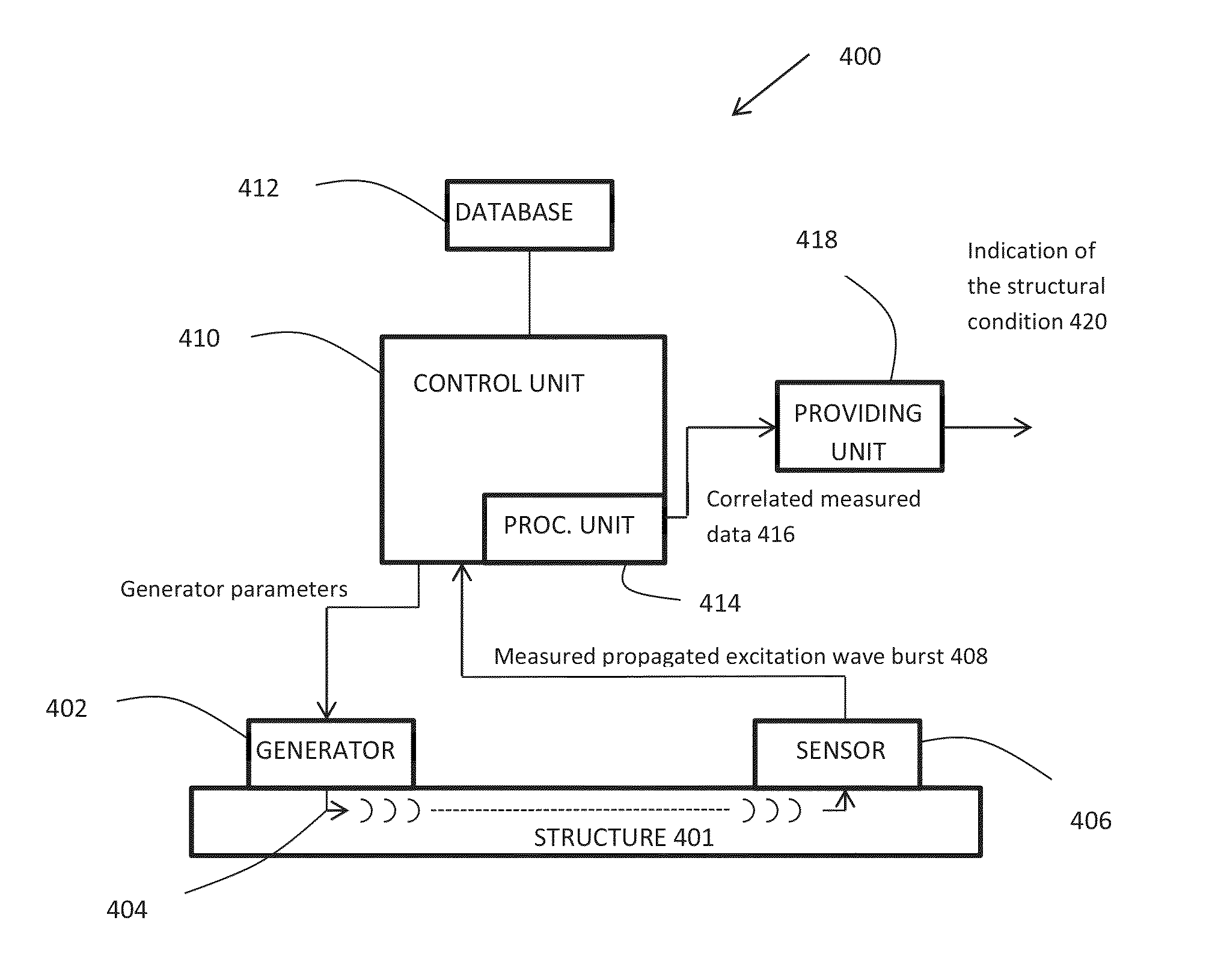
The invention relates to a method for providing a structural condition of a structure, comprising providing an excitation wave generator; providing an excitation wave sensor; injecting an excitation burst wave into the structure using the excitation wave generator; obtaining a measured propagated excitation burst wave using the excitation wave sensor; correlating the measured propagated excitation burst wave with one of a plurality of theoretical dispersed versions of the excitation burst wave; and providing an indication of the structural condition of the structure corresponding to the correlated measured propagated excitation burst wave. The method may offer a better localization of the reflection points and thus of the potential defects present in a structure under inspection, when compared with a group velocity-based or time-of-flight (ToF) approach. The method may be particularly useful for structural health monitoring (SHM) and Non-Destructive Testing (NDT). The method may also enable determination of the mechanical properties of the structure.

Description

CROSS REFERENCE TO RELATED APPLICATIONS[0001]This application claims priority of U.S. Provisional Patent Application Ser. No. 61 / 310,996 filed on Mar. 5, 2010 and entitled “METHOD FOR IMAGING A STRUCTURAL CONDITION OF A STRUCTURE”, the specification of which is hereby incorporated by reference.FIELD OF THE INVENTION[0002]The invention generally relates to imaging techniques and more particularly relates to a method and an apparatus for imaging a structural condition of a structure. It also relates to applications of the method for Structural Health Monitoring (SHM) and Non-Destructive Testing (NDT).BACKGROUND OF THE INVENTION[0003]Different imaging techniques have been developed for monitoring and control purposes.[0004]For example, because of their extended area inspection and their small wavelength, which better interacts with small defects, Structural Health Monitoring (SHM) techniques based on guided wave propagation in structures have been used for many years.[0005]The reflecti...

Claims


Application Information

Patent Timeline
IPC IPC(8): G01N29/04
CPCG01N29/069G01N29/226G01N2291/044G01N29/343G01N2291/0256G01N29/2475G01N29/07G01N29/30G01N29/4427G01N2291/0258G01N2291/101G01N2291/102
Inventor MASSON, PATRICEMICHEAU, PHILIPPEQUAEGEBEUR, NICOLASLANGLOIS DEMERS, DOMINIQUE
Owner SCOPRA SCI & GENIE SEC
Learn More