
Coriolis gyroscope having correction units and method for reducing the quadrature bias

a gyroscope and correction unit technology, applied in the field of gyroscopes, can solve the problems of marked noticeable errors in the rotation rate signal, two signal portions that are difficult to separate, and the manufacturing tolerance can lead to misalignment, so as to reduce the contribution of misalignmen

Active Publication Date: 2013-03-07
NORSROP GRUMAN LITEF GMBKH
View PDF11 Cites 16 Cited by
  • Summary
  • Abstract
  • Description
  • Claims
  • Application Information

AI Technical Summary

Benefits of technology

The present invention aims to reduce the contribution of misalignments to the quadrature bias in Coriolis gyroscopes and in systems of Coriolis gyroscopes coupled to one another. The invention achieves this without having to rotate and / or deflect the Coriolis mass. The invention also provides methods for reducing the quadrature bias in each individual gyroscope, and in a system of at least two Coriolis gyroscopes, by using correction units with stationary and moving correction electrodes that address the issue of offset misalignments. The technical effect of the invention is to improve the accuracy and reliability of Coriolis gyroscopes and their systems.

Problems solved by technology

In a multiple-part mass system, manufacturing tolerances can lead to misalignment (e.g. of the two resonators of a two-part single resonator).
Usually, quadrature signal portions (quadrature bias, quadrature signal, quadrature error) are much larger than those from the desired rotation rate resolution, making the two signal portions difficult to separate.
Due to the large difference between the signal portions, even small phase shifts lead to marked noticeable errors in the rotation rate signal (zero-point error, bias).

Method used


Image

  • Coriolis gyroscope having correction units and method for reducing the quadrature bias
  • Coriolis gyroscope having correction units and method for reducing the quadrature bias
  • Coriolis gyroscope having correction units and method for reducing the quadrature bias

Examples


Embodiment Construction

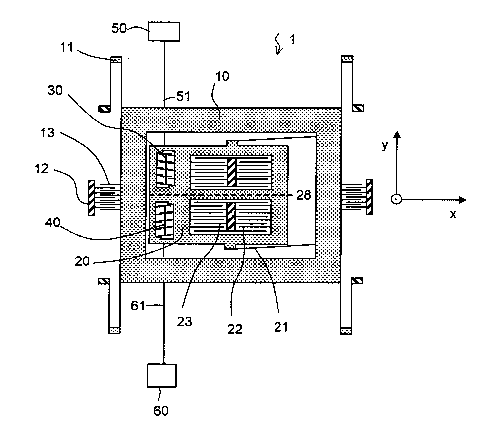
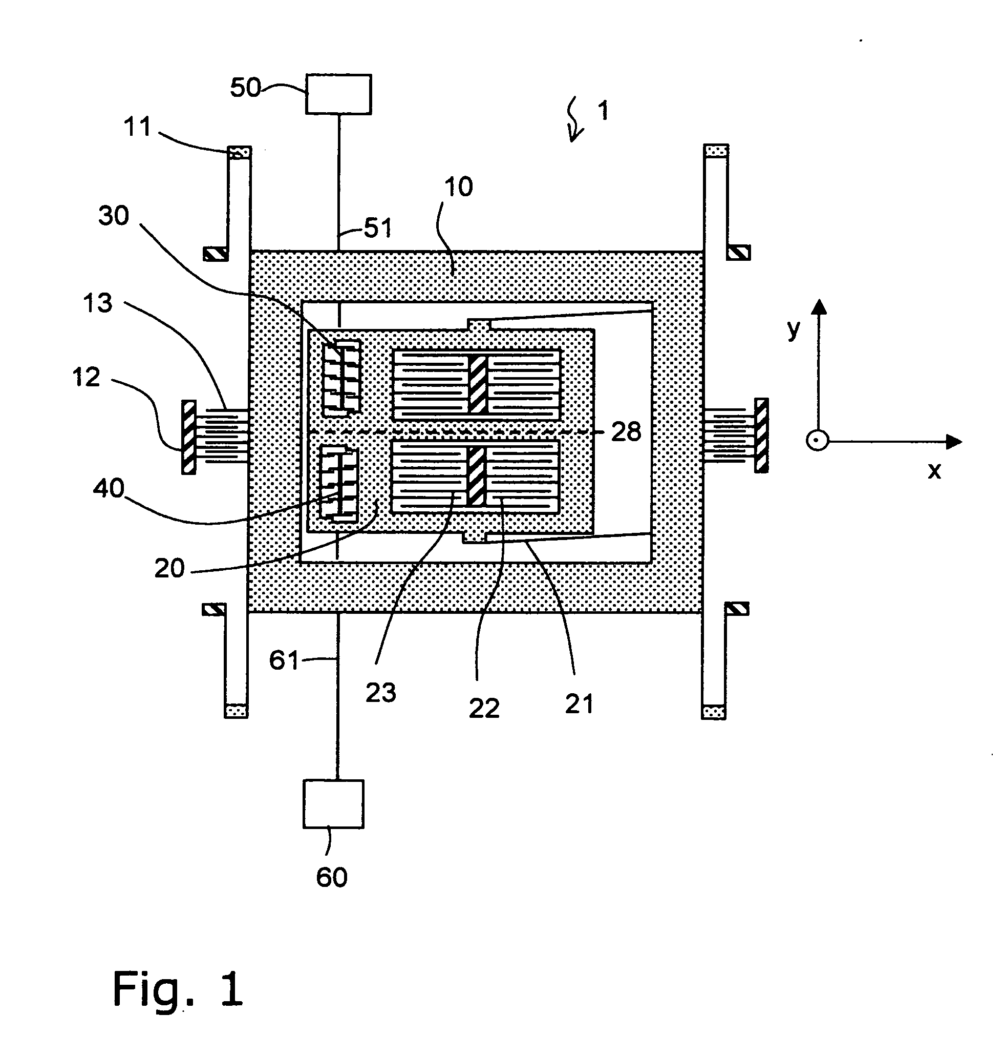
[0024]FIG. 1 is a schematic top view of a Coriolis gyroscope 1 having a single two-part resonator according to the invention. The linear single resonator is preferably manufactured by etching processes from a silicon disk and comprises a first part-mass 10 (drive frame), a second part-mass 20 (Coriolis mass), first spring elements 11 and second spring elements 21. The drive frame 10 is connected by the first spring elements 11 to a substrate that is positioned beneath the part-masses 10, 20. The first spring elements 11 are provided so that the first part-mass 10 and the second part-mass 20 can vibrate jointly along a first axis (x direction). The Coriolis mass 20 is connected by the second spring elements 21 to the first part-mass 10 and is suspended in such manner that it can vibrate with respect to the first part-mass 10 along a second axis (y direction) that is perpendicular to the first axis.

[0025]The spring elements 21 are not limited to a specific design.

[0026]The first and t...


PUM


Abstract

A Coriolis gyroscope comprises a mass system that can be excited to perform vibrations parallel to a first axis, whereby a deflection of the mass system due to a Coriolis force along a second axis perpendicular to the first axis is detectable. At least one first correction unit and at least one second correction unit, which each comprise a plurality of stationary correction electrodes and moving correction electrodes whereby the stationary correction electrodes extend in the direction of the first axis and are firmly connected to the substrate by corresponding anchor structures, and the moving correction electrodes are provided as a part of the mass system. A method for reducing the quadrature bias of a Coriolis gyroscope of this type comprises applying at least temporarily constant corrective voltages to the correction units.

Description

BACKGROUND[0001]1. Field of the Invention[0002]The present invention relates to Coriolis gyroscopes. In particular, this invention pertains to a Coriolis gyroscope, a system of Coriolis gyroscopes and a method in which, and whereby, quadrature bias is reduced.[0003]2. Description of the Prior Art[0004]Coriolis gyroscopes (vibration gyroscopes, rotation rate sensor) comprise one or multi-part mass systems that are made to vibrate. A first vibration mode (excitation vibration) of the mass system is excited to operate the Coriolis gyroscope. If the Coriolis gyroscope is subjected to rotary motion about its sensitive axis, the Coriolis forces that occur excite a second vibration mode of the mass system, which is detected directly or indirectly, whereby a read-out signal reflecting the second vibration mode is obtained. The read-out signal is analyzed for changes in amplitude which are a measure of the rotation rate applied to the Coriolis gyroscope. In a closed-loop Coriolis gyroscope, ...

Claims


Application Information

Patent Timeline
IPC IPC(8): G01C25/00G01C19/5755
CPCG01C19/5755G01C25/00G01C19/56
Inventor GEIGER, WOLFRAMLEINFELDER, PETER
Owner NORSROP GRUMAN LITEF GMBKH
Learn More