Vehicle-body structure of vehicle and manufacturing method of the same

Active Publication Date: 2013-02-28
MAZDA MOTOR CORP
View PDF7 Cites 14 Cited by
  • Summary
  • Abstract
  • Description
  • Claims
  • Application Information

AI Technical Summary

Benefits of technology

The present invention provides a vehicle-body structure and manufacturing method that can improve the comfortable ride and reduce the noises of a vehicle by proper restraint of vibration transmission and ensuring sufficient rigidity of the vehicle-body structure. The reinforcing member is provided in the closed-section portion formed by a single vehicle-body forming member or multiple vehicle-body forming members joined together, which can improve the rigidity of the vehicle-body forming member and reduce vibrations. The joint portion of the vehicle-body forming member and the reinforcing member includes both a rigid joint portion and a flexible joint portion, which helps reduce vibrations and prevent deformation of the vehicle-body forming member. The joint portion can be effectively positioned at the dent portion of the closed-section portion where a stress concentration occurs easily or at the flange portion of the bulkhead to ensure joing strength and provide a vibration-damping effect. The manufacturing method includes a rigid joining step and a flexible joining step via a damping member. The vehicle-body structure made by this method can provide the same effects as the present invention without adding extra weight or strain on the vehicle body.

Problems solved by technology

According to the structures disclosed in the above-described patent publications, however, there is a concern that while improvement of the rigidity is achieved, vibrations occurring at various portions of the vehicle may not be effectively restrained from transmitting to the inside of the vehicle compartment in some cases depending on arrangement positions, shapes, and the like.

Method used


Image

  • Vehicle-body structure of vehicle and manufacturing method of the same
  • Vehicle-body structure of vehicle and manufacturing method of the same
  • Vehicle-body structure of vehicle and manufacturing method of the same

Examples


first embodiment

[0051]FIG. 8 is a perspective view showing the bulkhead as the reinforcing member according to the present invention. FIG. 8 shows a state in which a damping member is attached to the bulkhead. The bulkhead 20 comprises, as shown in FIG. 8, a partition face portion 21 which partitions the closed-section portion 11f, a first flange portion 32 which is provided at an upper side portion of the partition face portion 21 and extends rearward, second and third flange portions 23, 24 which are provided at a vehicle-outside side portion of the partition face portion 21 and extend rearward, and a fourth flange portion 25 which is provided at a vehicle-inside side portion of the partition face portion 21 and extends forward. A seat portion 25a is formed at the fourth flange portion 25 in a recess shape so as to accommodate viscoelastic members 27 therein, which will be described. Herein, a hole portion 26 is formed at the partition face portion 21 for weight reduction.

[0052]The first, second ...

second embodiment

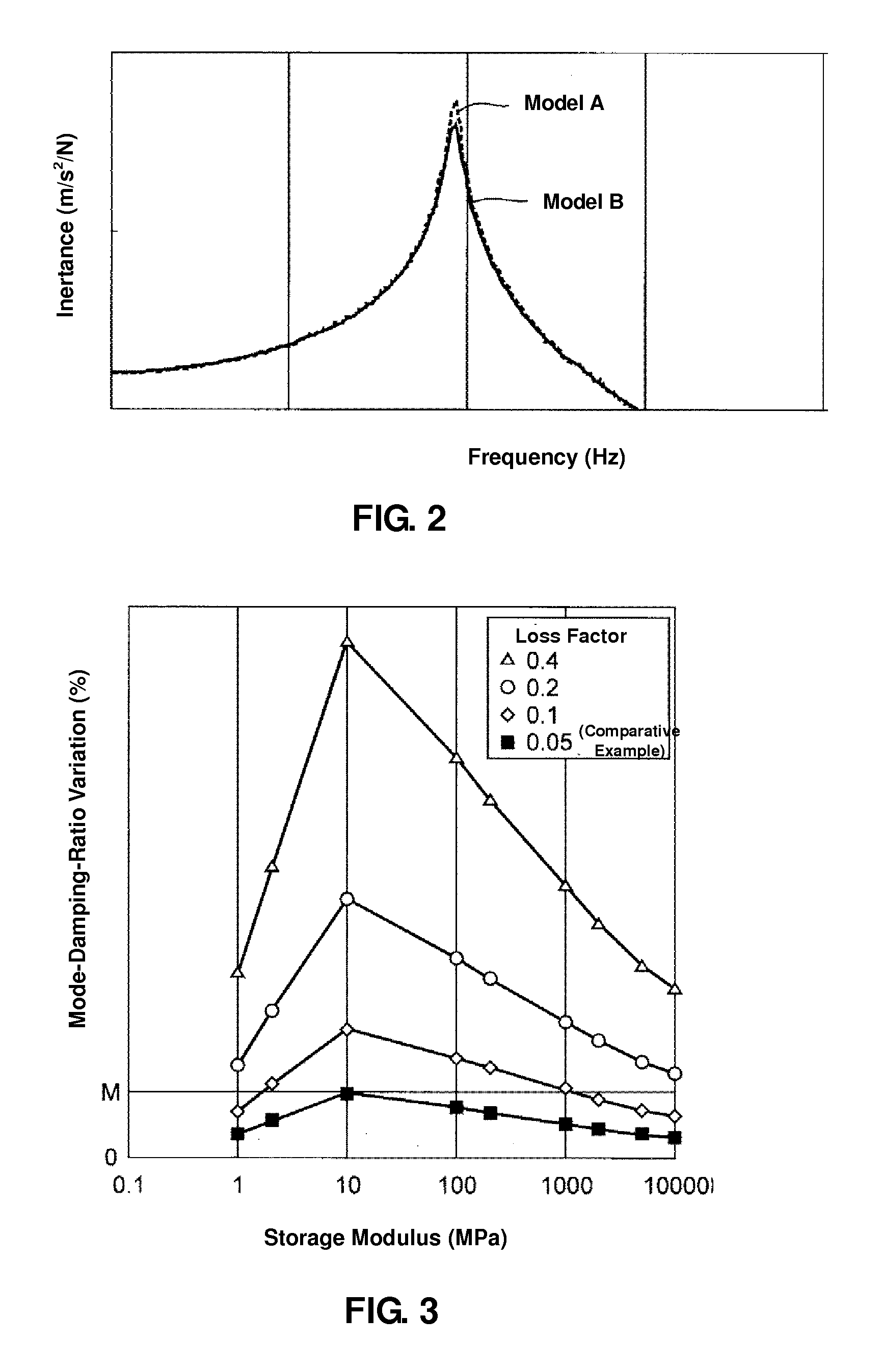
[0054]Herein, the viscoelastic member 27 having the physical properties which fall within the range enclosed by six coordinate points: (1, 0.4), (1, 0.2), (2, 0.1), (1000, 0.1), (10000, 0.2) and (10000, 0.4) in the X-Y coordinate system with X axis of the storage modulus and Y axis of the loss factor, or the range exceeding the loss factor of 0.4 may be preferably used. A viscoelastic member similar to the above-described viscoelastic member 27 may be preferably used in a second embodiment which will be described below.

[0055]While the hollow frame formed by the roof rail inner 11a and the roof rail reinforcement 11c and the bulkhead 20 are joined together at the dent portion 11d denting toward the inside of the closed-section portion of the roof rail inner 11a in the present embodiment, they may be joined together at a position which is located in the vicinity of the dent portion 11d.

[0056]Further, while the bulkhead 20 is joined in the closed-section portion 11f formed by the roof...


PUM

PropertyMeasurementUnit
Structureaaaaaaaaaa
Flexibilityaaaaaaaaaa

Abstract

In a vehicle-body structure of a vehicle which comprises vehicle-body forming members forming a closed-section portion and having a dent portion which dents toward an inside of the closed-section portion, and a reinforcing member provided in the closed-section portion and joined to the vehicle-body forming members, a joint portion of the vehicle-body forming members and the reinforcing member includes a rigid joint portion where the vehicle-body forming members and the reinforcing member are joined with a direct contact thereof and a flexible joint portion where the vehicle-body forming members and the reinforcing member are joined via a damping member provided therebetween, and this joint portion is provided at or in the vicinity of the dent portion.

Description

BACKGROUND OF THE INVENTION[0001]The present invention relates to a vehicle-body structure of a vehicle and a manufacturing method of the same.[0002]Vehicles, such as automotive vehicles, are required to increase the rigidity of a vehicle body in order to improve the comfortable ride and the safety. Japanese Utility Model Laid-Open publication Nos. 59-182472 and 60-097673, for example, disclose structures for increasing the rigidity of the vehicle body in which a reinforcing member is provided in a closed-section portion formed by a vehicle-body forming member.[0003]The first one of the above-described patent publications discloses the structure in which the bulkhead is arranged in a bamboo-joint shape in the closed-section portion of the side sill formed by the side sill outer and the side sill inner, and the flanges formed at its periphery are joined to the inner faces of the side sill outer and the side sill inner by both spot welding and an adhesive agent.[0004]The second one of...

Claims


Application Information

Patent Timeline
IPC IPC(8): B62D25/00B23P17/00
CPCB62D25/02Y10T29/49622B62D25/2027B62D25/088
Inventor KUROGI, OSAMUSUGIHARA, TSUYOSHINAKAGAWA, KOHYANAGAO, KUNIAKITERADA, SAKAYUKOWAKI, MIHOIYOSHI, AKIRAWATANABE, SHIGEAKI
Owner MAZDA MOTOR CORP
Why Eureka
Try Eureka