
Bearing assembly for a vertical turbine pump

a vertical turbine pump and bearing technology, applied in the direction of machines/engines, mechanical equipment, liquid fuel engines, etc., can solve the problems of reducing pumping efficiency and excessive vibration, pump must be taken out of service for significant repair, and the adjacent surface of the rotating drive shaft and the bearing is worn, etc., to achieve the effect of improving the comprehensive contact of the lip seal, improving the service life and increasing the strength of the lip seal

Active Publication Date: 2013-02-21
WEIR FLOWAY
View PDF6 Cites 8 Cited by
  • Summary
  • Abstract
  • Description
  • Claims
  • Application Information

AI Technical Summary

Benefits of technology

The bearing assembly described in this patent has a pressure equalization element to prevent wear and tear on the sealing elements. This improves the service life of the sealing elements and the bearing assembly, and eliminates the need for costly and potentially inefficient flushing systems. Overall, this improvement helps to increase the efficiency and reliability of vertical turbine pumps.

Problems solved by technology

While lubrication systems of the type described in the prior art are satisfactory for use in pumping applications where the fluid being pumped is clear liquid or liquid with very low solids content, these systems are problematic in applications where the fluid being pumped contains solids or particulate matter.
The solids in the pumping fluid are abrasive and cause a wearing of the adjacent surfaces of and between the rotating drive shaft and the bearing.
The degradation of the bearings results in reduced pumping efficiency and excessive vibration, and the pump must eventually be taken out of service for significant repair.
However, such clean fluid flushing systems are not always available given certain factors like pumping location.
Furthermore, the use of clean flushing fluid can add significant operational costs.
However, such enclosed lineshaft bearing systems, while useful for the lineshaft, cannot be used for bowl or pump casing bearings.

Method used


Image

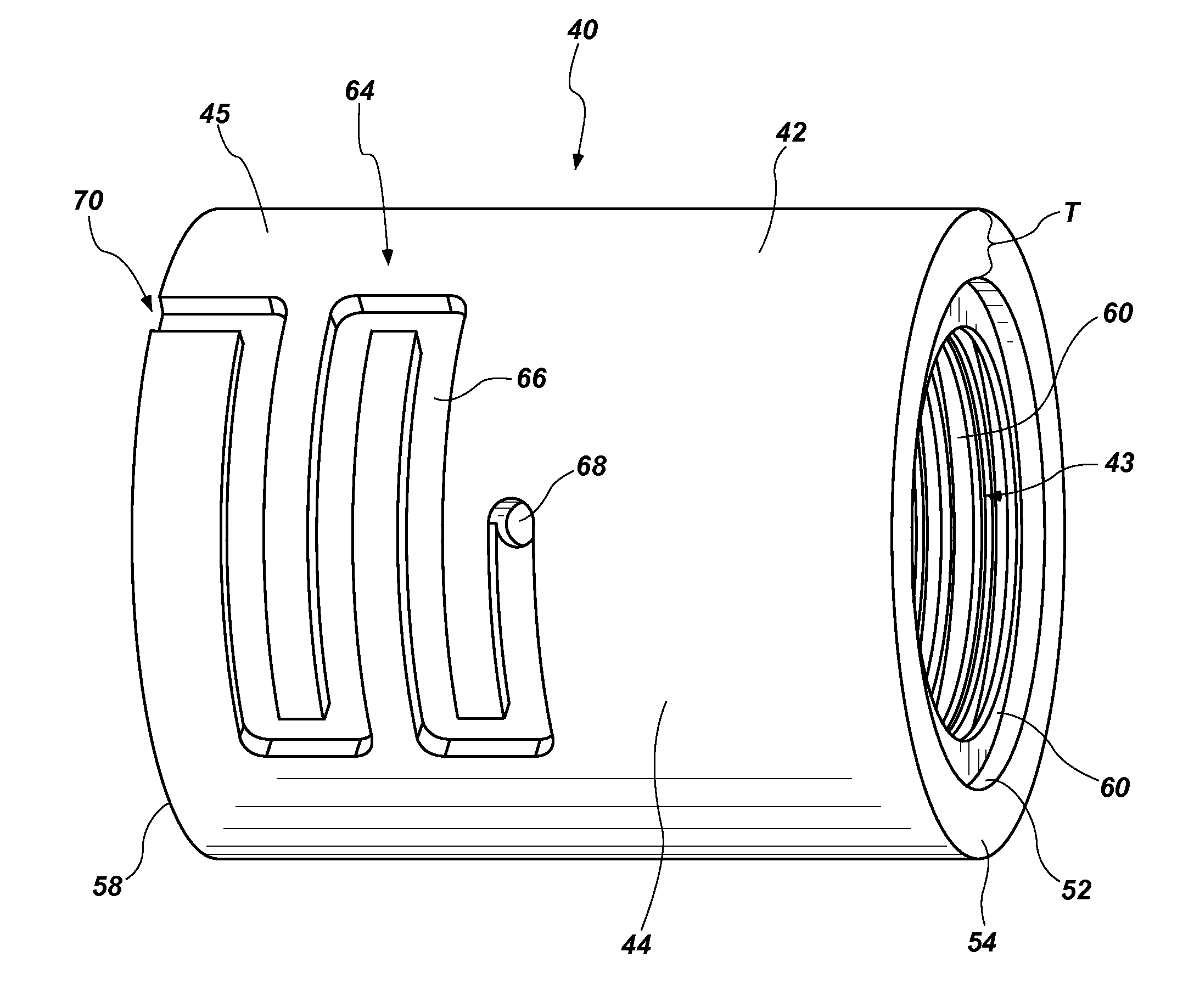
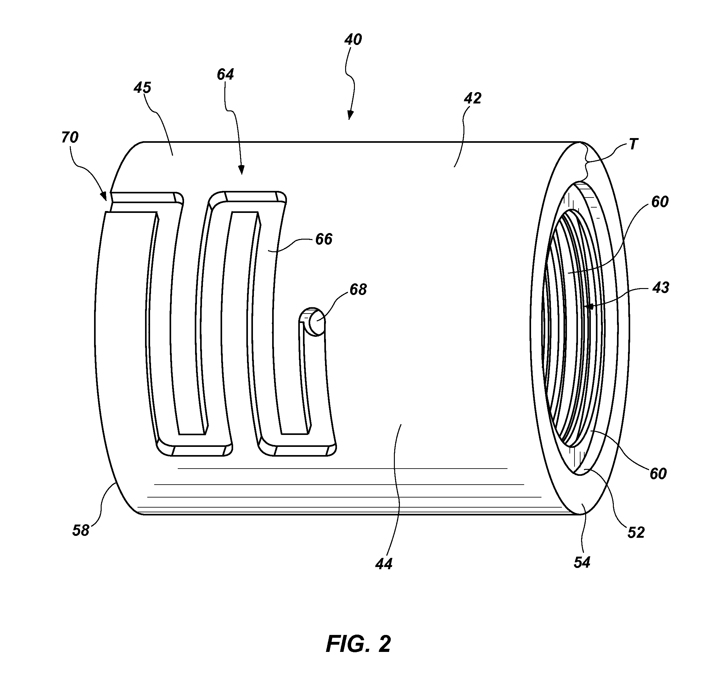
  • Bearing assembly for a vertical turbine pump
  • Bearing assembly for a vertical turbine pump
  • Bearing assembly for a vertical turbine pump

Examples


Embodiment Construction

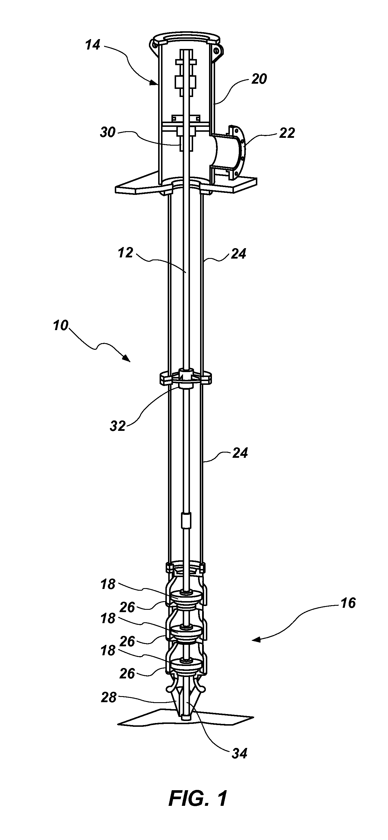
[0079]While the bearing assembly disclosed herein may be adaptable for use in any number of varieties of pumps, the bearing assembly is described herein with respect to its placement in a vertical turbine pump, as one example. FIG. 1 depicts the general structure of a multistage vertical turbine pump of the type in which the bearing of the disclosure is suitably used. The vertical turbine pump 10 is generally structured with a drive shaft 12 that extends from a first end 14, comprising a drive end, to a second end 16, comprising a suction end. A drive motor (not shown) is positioned near the first end 14 of the drive shaft 12 to which the drive shaft is operatively coupled to effect rotation of the drive shaft. At the second end 16 of the drive shaft 12 is positioned one or more impellers 18, three such impellers being illustrated in a multistage configuration as depicted in FIG. 1.

[0080]The drive shaft 12 extends from a discharge head assembly 20, which includes a discharge outlet ...


PUM


Abstract

A bearing assembly for supporting a drive shaft of a pump is structured with a cylindrical body having an internal cavity filled with a lubricant, a sealing element arrangement positioned at one or both ends of the cylindrical body and a pressure equalization element that functions to equalize the pressure differential that exists between an area within the cylindrical body and outside of the cylindrical body to improve the operating life of the sealing arrangement and the bearing assembly.

Description

CROSS REFERENCE TO RELATED APPLICATIONS[0001]This application is a non-provisional application claiming priority to U.S. provisional application Ser. No. 61 / 523,949, filed Aug. 16, 2011, the contents of which are incorporated herein in their entirety.TECHNICAL FIELD[0002]This disclosure relates to vertical turbine pumps of the type used in the pumping of water or other fluids from wells and sumps, and through pipelines, and specifically relates to a bearing assembly for supporting a drive shaft that drives one or more impellers of the pump.BACKGROUND OF THE DISCLOSURE[0003]Vertical turbine pumps are commonly used in a variety of industries to pump water or other fluids from a source below ground level, such as a well or sump. Another common application of vertical turbine pumps is in a pressure boosting configuration in a pipeline. Typical industries in which vertical turbine pumps are used include agriculture, water / wastewater, industrial, oil & gas and mining.[0004]Vertical turbin...

Claims


Application Information

Patent Timeline
Patent Type & Authority Applications(United States)
IPC IPC(8): F01D25/16
CPCF01D25/166F04D29/047F04D1/063F01D25/186
Inventor BOLDT, DANIEL E.
Owner WEIR FLOWAY
Learn More