
Moving object detection method using image contrast enhancement

a technology of image contrast and moving object, applied in image enhancement, image analysis, instruments, etc., can solve the problems of only recording images, failure of intelligent surveillance systems, and inability to analyze objects or events, so as to facilitate change detection and background and foreground separation, save computational resources, and improve processing efficiency

Inactive Publication Date: 2013-02-21
VATICS
View PDF4 Cites 54 Cited by
  • Summary
  • Abstract
  • Description
  • Claims
  • Application Information

AI Technical Summary

Benefits of technology

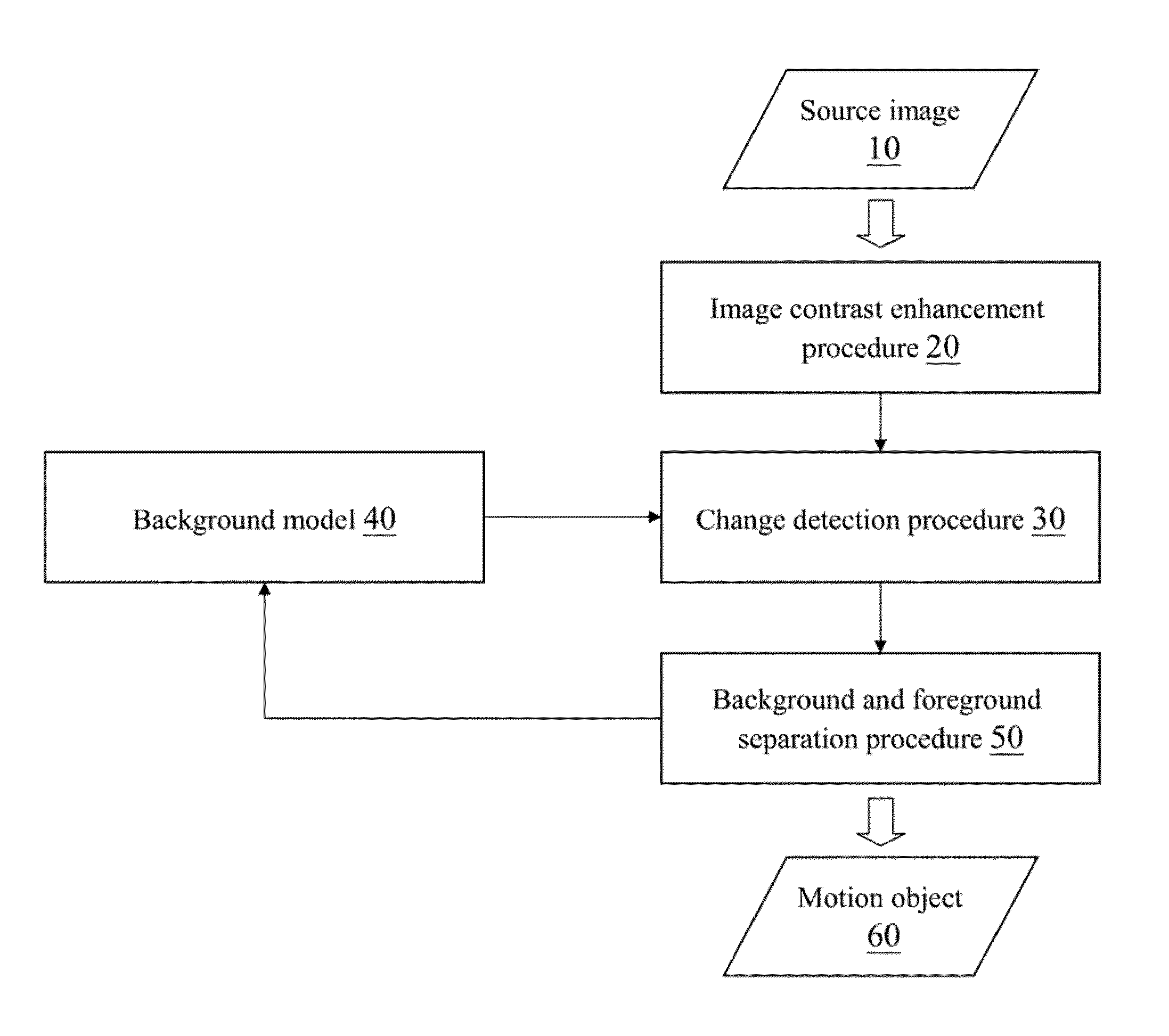
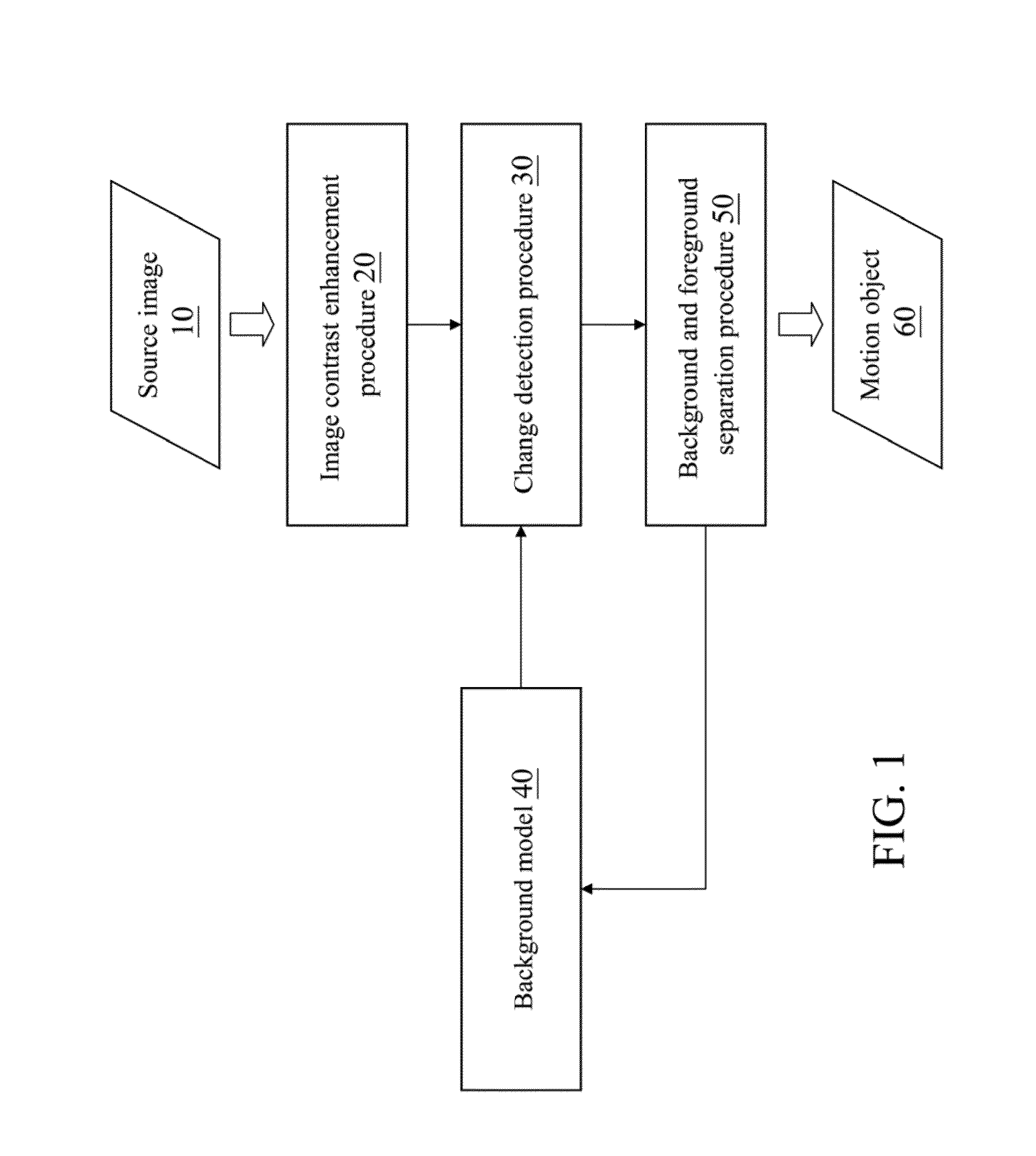
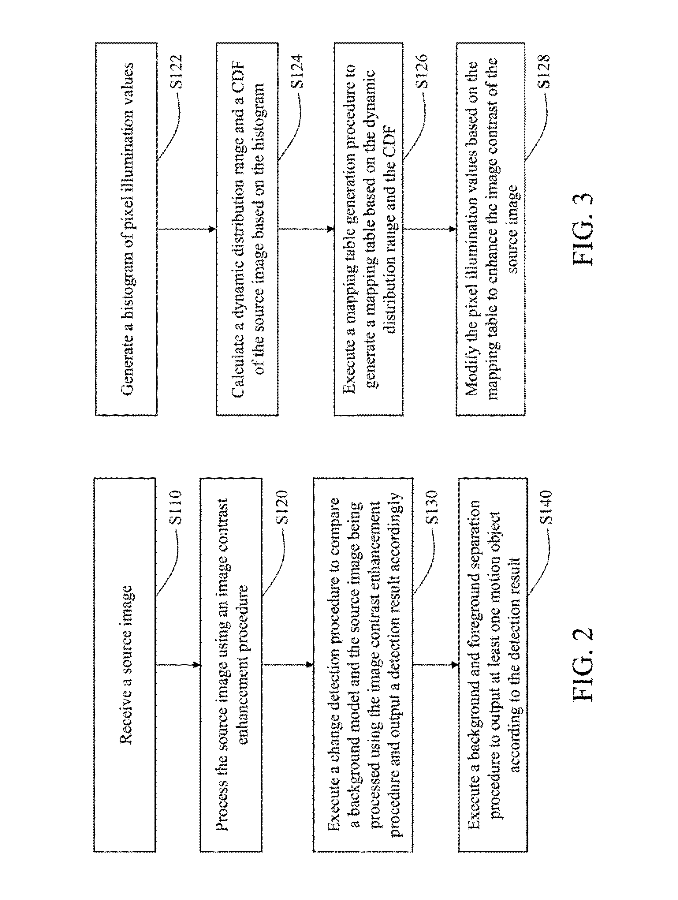
The disclosure is about a method for detecting moving objects using image contrast enhancement. This method involves generating a histogram of pixel illumination values, creating a dynamic distribution range and cumulative distribution function, and creating a mapping table based on these functions. Pixel illumination values are then modified to enhance the contrast of the source image. This method simplifies the comparison and compensation procedures used in previous approaches, resulting in improved processing efficiency and easier detection of changes and separation of background and foreground.

Problems solved by technology

However, a conventional surveillance system is only capable of recording images, but is incapable of analyzing an object or event.
However, when the image has high noises, poor image contrast, partial or global sudden illumination changes or shadows or is shot while weather condition changes, analysis errors occur easily, resulting in identification failure of the intelligent surveillance system.
However, the conventional approach may cause detection failures, inappropriate auto exposure (AE) manner for compensation and inappropriate settings of compensation reference points or threshold values, such that subsequent analysis errors still occur to the compensated image.

Method used


Image

  • Moving object detection method using image contrast enhancement
  • Moving object detection method using image contrast enhancement
  • Moving object detection method using image contrast enhancement

Examples


Embodiment Construction

[0027]The detailed features and advantages of the disclosure are described below in great detail through the following embodiments, the content of the detailed description is sufficient for those skilled in the art to understand the technical content of the disclosure and to implement the disclosure there accordingly. Based upon the content of the specification, the claims, and the drawings, those skilled in the art can easily understand the relevant objectives and advantages of the disclosure.

[0028]The disclosure relates to a moving object detection method using image contrast enhancement for detecting at least one moving object in a source image in various situations such as a condition of fierce illumination changes.

[0029]The image contrast enhancement method and the moving object detection method using image contrast enhancement may be implemented, for example, by a surveillance system. The surveillance system captures at least one source image with an image detector and uses a ...


PUM


Abstract

A moving object detection method using image contrast enhancement includes receiving a source image, in which each pixel has a pixel illumination value; processing the source image using an image contrast enhancement procedure; executing a change detection procedure to compare a background model and the source image being processed using the image contrast enhancement procedure, and outputting a detection result accordingly; and executing a background and foreground separation procedure to output a moving object according to the detection result. The image contrast enhancement procedure may include generating a histogram of pixel illumination values; calculating a dynamic distribution range and a cumulative distribution function (CDF) of the source image based on the histogram; executing a mapping table generation procedure to generate a mapping table based on the dynamic distribution range and the CDF; and modifying pixel illumination values based on the mapping table to enhance image contrast of the source image.

Description

CROSS-REFERENCE TO RELATED APPLICATIONS[0001]This non-provisional application claims priority under 35 U.S.C. §119(a) on Patent Application No(s). 100129855 filed in Taiwan, R.O.C. on Aug. 19, 2011, the entire contents of which are hereby incorporated by reference.BACKGROUND[0002]1. Technical Field[0003]The disclosure relates to a moving object detection method with image contrast enhancing steps, and more particularly to an image contrast enhancement method using a histogram and a moving object detection method employing the image contrast enhancement.[0004]2. Related Art[0005]An image processing method may be used in various fields. For example, the image processing method may be applied in video surveillance or security monitoring service. Taking video surveillance as an example, in the past decade, the closed-circuit video surveillance system has been used for safety related purposes. However, a conventional surveillance system is only capable of recording images, but is incapab...

Claims


Application Information

Patent Timeline
IPC IPC(8): G06K9/00
CPCH04N7/18G06T5/009G06T2207/20144G06T7/2053G06T5/40G06T7/254G06T7/194G06T5/92
Inventor CHERNG, DER-CHUNLU, YAN-CHEN
Owner VATICS
Learn More