Sliding element, in particular piston ring, and combination of a sliding element with a mating running element
a technology of sliding element and running element, which is applied in the direction of superimposed coating process, chemical vapor deposition coating, braking system, etc., can solve the problems of friction loss deterioration and wear resistan
- Summary
- Abstract
- Description
- Claims
- Application Information
AI Technical Summary
Benefits of technology
Problems solved by technology
Method used
Image

Examples
Embodiment Construction
[0008]The invention is based on the object of providing a sliding element, in particular a piston ring, which in particular when used in diesel or highly supercharged spark-ignition engines with, for example, iron-based mating running elements, fulfils the requirements with respect to service life and friction loss. It will also disclose a suitable combination of a sliding element with mating running element.
[0009]This object is achieved by the sliding element described in claim 1.
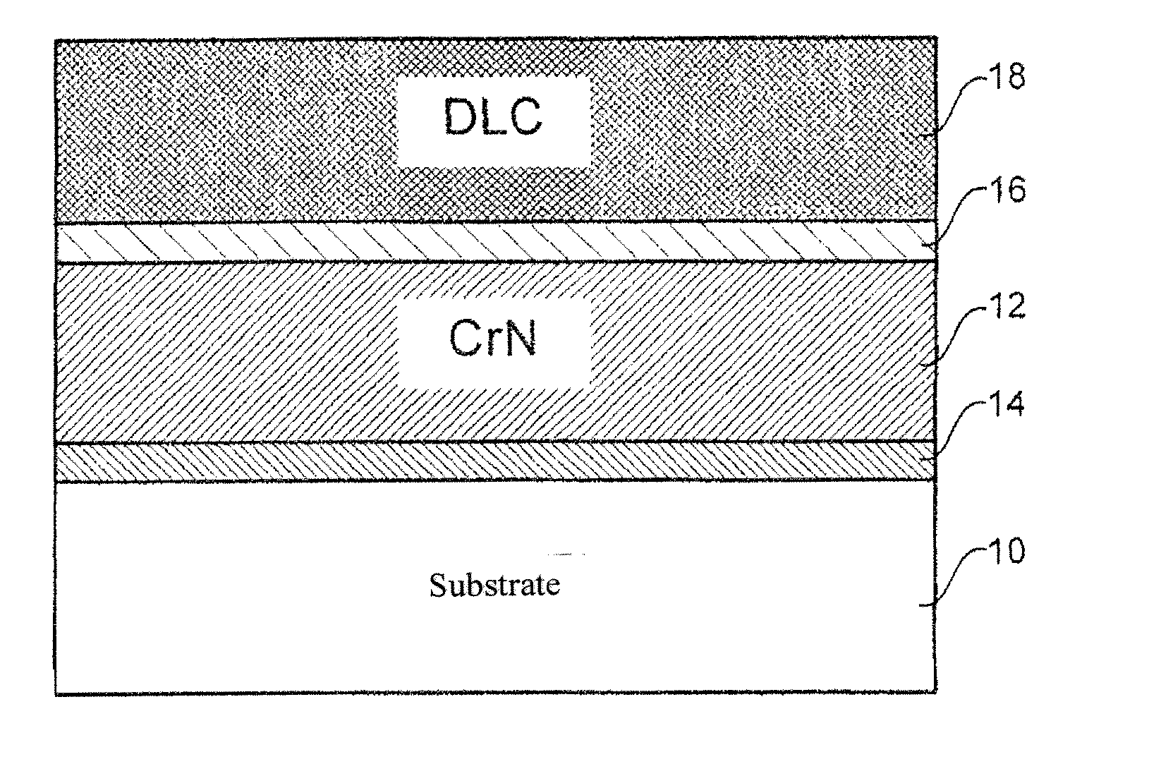
[0010]This sliding element is characterised, on the one hand, by a combination of a CrN layer and a DLC layer on the outer side. The DLC layer is either metal-free or comprises a metal-containing substructure and a metal-free DLC top layer. In other words, the DLC layer is at least partially metal-free and, in particular on the outer surface, comprises a metal-free DLC layer. Moreover, extensive tests have shown that the coating described displays particularly good characteristics if a Me(CxNy) layer is pr...
PUM
| Property | Measurement | Unit |
|---|---|---|
| thickness | aaaaa | aaaaa |
| thickness | aaaaa | aaaaa |
| thickness | aaaaa | aaaaa |
Abstract
Description
Claims
Application Information
 - Generate Ideas
- Intellectual Property
- Life Sciences
- Materials
- Tech Scout
- Unparalleled Data Quality
- Higher Quality Content
- 60% Fewer Hallucinations
Browse by: Latest US Patents, China's latest patents, Technical Efficacy Thesaurus, Application Domain, Technology Topic, Popular Technical Reports.
© 2025 PatSnap. All rights reserved.Legal|Privacy policy|Modern Slavery Act Transparency Statement|Sitemap|About US| Contact US: help@patsnap.com