High voltage DC breaker apparatus

Active Publication Date: 2013-02-14
HITACHI ENERGY SWITZERLAND AG
View PDF5 Cites 17 Cited by
  • Summary
  • Abstract
  • Description
  • Claims
  • Application Information

AI Technical Summary

Benefits of technology

The patent describes a new design for a mechanical DC breaker that reduces power transfer losses and the number of semiconductor devices needed during normal operation. By allowing the current limiting arrangement to handle most of the current, the semiconductor devices only need to limit fault current levels. This results in a lower protective voltage level for the current limiting arrangement, which can be achieved by using a series connection of inductance and capacitance in parallel with the mechanical switch. Overall, this design not only reduces power transfer losses but also simplifies the control scheme and reduces costs.

Problems solved by technology

Although such solid state DC breakers, i.e. based on semiconductor switches, respond almost instantaneously to the demand of the control and protection system, a disadvantage of such a breaker apparatus is that it has a large number of semiconductor devices, such as IGBT:s, to be connected in series for being able to take a voltage corresponding to the protective voltage of the arrester banks, which results in considerable costs and also power transfer losses when the current of the DC conductor flows through the semiconductor devices.
The disadvantage of such existing mechanical DC breaker solutions is, however, the time delay between the control signal from the protection system and the breaking action.
Even with a modified standard AC breaker it will take 10-20 ms until the mechanical contacts are opened, which is too slow for application in a high voltage DC conductor, such as in a DC grid.

Method used


Image

  • High voltage DC breaker apparatus
  • High voltage DC breaker apparatus
  • High voltage DC breaker apparatus

Examples


second embodiment

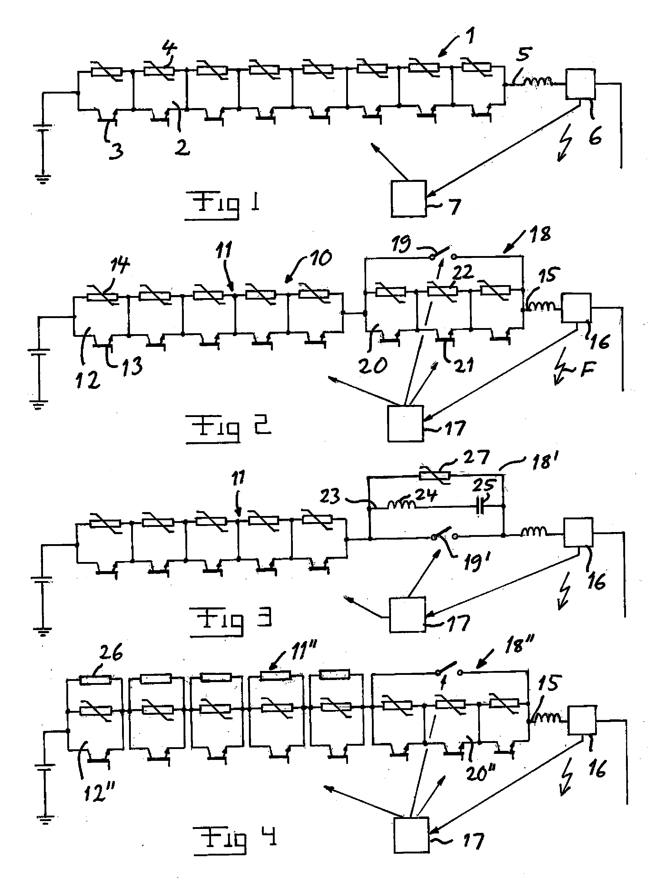
[0041]A high voltage DC breaker apparatus according to the invention is schematically illustrated in FIG. 3 and differs from the one shown in FIG. 2 by the design of the mechanical DC breaker 18′. This DC breaker has an LC-circuit 23 with an inductance 24 and a possibly precharged capacitance 25 connected in parallel with the mechanical switch 19′ and an arrester 27 connected in parallel with the LC-circuit. The control unit 17 is here configured to control breaking of a said fault current by opening said mechanical switch 19′ after having turned off the semiconductor devices 13 of the current limiting arrangement as for the embodiment shown in FIG. 2. The lower number of semiconductor devices required in the apparatus according to FIG. 3 with respect to the one according to FIG. 2 may result in a reduction of costs and a simplifying of the control of the apparatus.

third embodiment

[0042]A high voltage DC breaker apparatus according to the invention is schematically illustrated in FIG. 4 and differs from the one according to FIG. 2 only by the fact that each section 12″ of the current limiting arrangement 11″ has a resistor 26 connected in parallel with each arrester, so that power losses resulting from a high fault current may be dissipated through the resistors, so that a cost efficient increase of the energy absorbing capability of the apparatus is thus obtained. In this case the protective voltage level of the current breaking part, i.e. the mechanical DC breaker 18″, must exceed the DC voltage level of the conductor 15 with respect to ground, and a typical such protective voltage level is 150% of the latter.

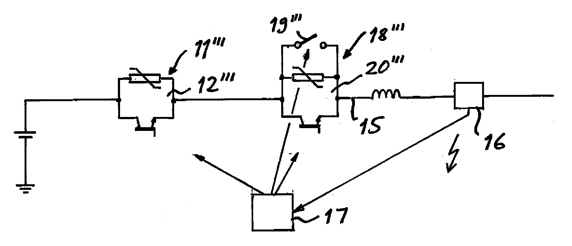
[0043]Finally, FIG. 5 schematically illustrates the most simple design of a high voltage DC breaker apparatus according to the present invention, which has a current limiting arrangement 11′″ with only one said section 12′″ and a mechanical DC breaker ...


PUM


Abstract

A high voltage DC breaker apparatus configured to break a fault current occurring in a high voltage DC conductor includes a current limiting arrangement having at least one section with at least one semiconductor device of turn-off type and at least one arrester connected in parallel therewith, and a mechanical DC breaker connected in series with the current limiting arrangement and including a mechanical switch. The mechanical DC breaker is configured to enable breaking of a fault current in said DC conductor once said semiconductor devices of said arrangement have been turned off.

Description

FIELD OF THE INVENTION AND BACKGROUND ART[0001]The invention relates to a high voltage DC breaker apparatus configured to break a fault current occurring in a high voltage DC conductor, said apparatus comprising[0002]a current limiting arrangement having at least one section with at least one semiconductor device of turn-off type and at least one arrester connected in parallel therewith, said at least one section being configured to be connected in series with said DC conductor,[0003]means configured to detect occurrence of a fault current in said DC conductor, and[0004]a unit configured to control breaking of said fault current upon detection of occurrence thereof, said control including turning off all semiconductor devices of said arrangement.[0005]High voltage means a voltage ≧10 kV and often a voltage of several hundreds kV with respect to ground.[0006]Such a high voltage DC breaker apparatus may be arranged in a high DC voltage carrying system for obtaining breaking of fault c...

Claims


Application Information

Patent Timeline
IPC IPC(8): H02H9/08
CPCH01H9/548H01H33/596H02H9/025H01H2009/544H02H3/025H01H2009/543H02H3/08Y02E60/60
Inventor HAFNER, JURGENASPLUND, GUNNAR
Owner HITACHI ENERGY SWITZERLAND AG
Why Eureka
Try Eureka