Eureka AIR delivers breakthrough ideas for toughest innovation challenges, trusted by R&D personnel around the world.

Facility in particular for producing and processing fluids, including a floating unit provided with a system for single-point mooring

a technology for producing and processing fluids, applied in the direction of shafts and bearings, rotary bearings, bearings, etc., can solve the problems of complicated manufacturing of bearings of suitably large diameters and the difficulty of manufacturing bearing and carrier structure assemblies

Inactive Publication Date: 2013-02-07
TECH FRANCE SA
View PDF4 Cites 12 Cited by
  • Summary
  • Abstract
  • Description
  • Claims
  • Application Information

AI Technical Summary

Benefits of technology

The invention proposes a solution to the problem of excessive bending moments and bearing loads in the turret of a floating unit. The invention includes a radial bearing positioned above the turret, which receives and supports incoming fluid-transfer pipes. The upper bearing is inter-positioned between a bearing member of the turret and a supporting structure of the vessel. The upper bearing can be a single-piece ring or a combination of two rings. The bearing has a conical surface that allows for the rotation and lateral tilting movement of the turret. The bearing can be a plurality of rings or a combination of conical and cylindrical recirculating roller bearings. The installation can be characterized by the use of conical annular platforms, recirculating roller bearings, or elastically deformable wheels. The invention also includes a carrier structure that is connected to the vessel at three main points and adapted to uncouple the structure from the vessel's hull.

Problems solved by technology

However, the manufacture of bearings of suitably large diameter is complicated, and, in addition, consideration must be given at the designing stage to major structural deformations, subsidence, or out-of-round deformation.
The manufacture of bearing and carrier structure assemblies therefore proves to be difficult, and the preparation of bearing raceways in particular to obtain the required planarity and their installation entail numerous constraints.

Method used


Image

  • Facility in particular for producing and processing fluids, including a floating unit provided with a system for single-point mooring
  • Facility in particular for producing and processing fluids, including a floating unit provided with a system for single-point mooring
  • Facility in particular for producing and processing fluids, including a floating unit provided with a system for single-point mooring

Examples


Embodiment Construction

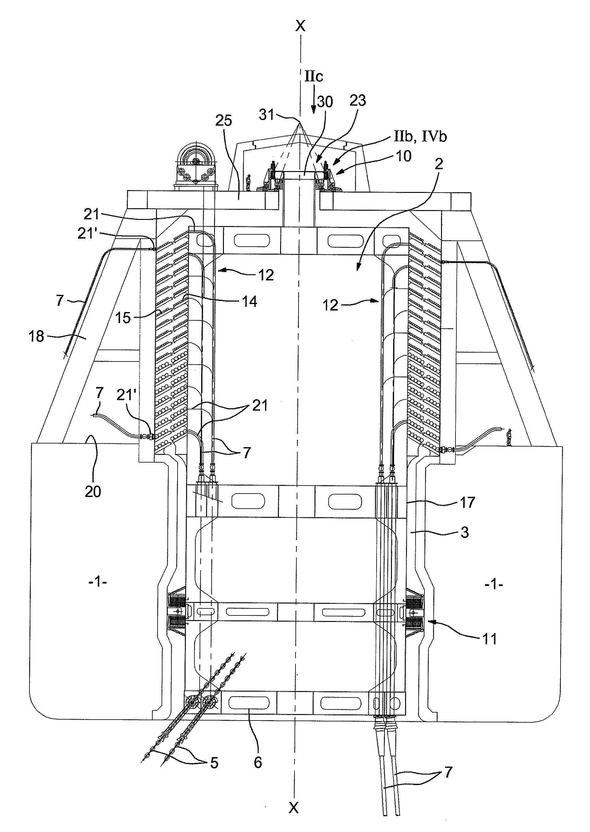
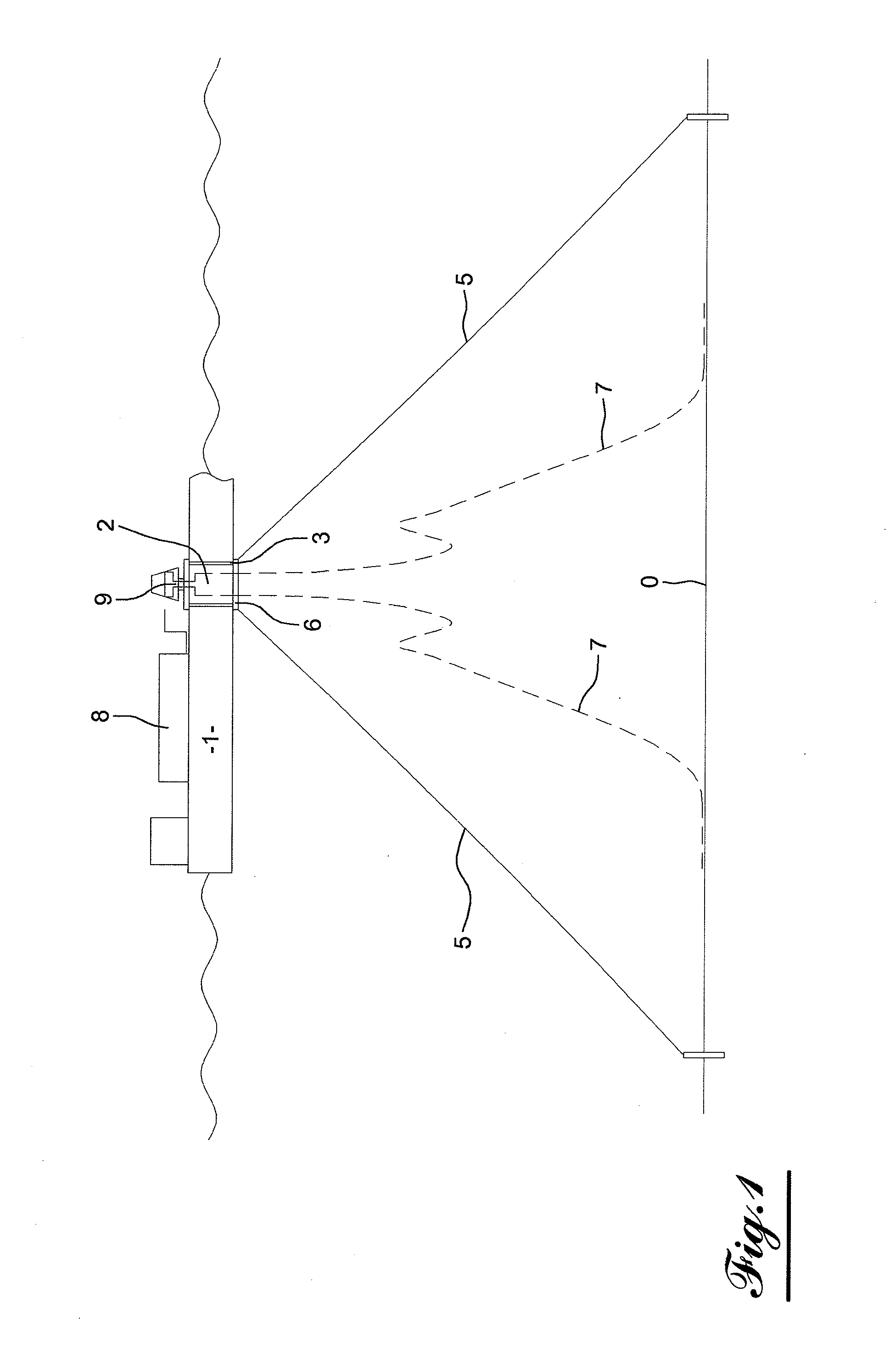
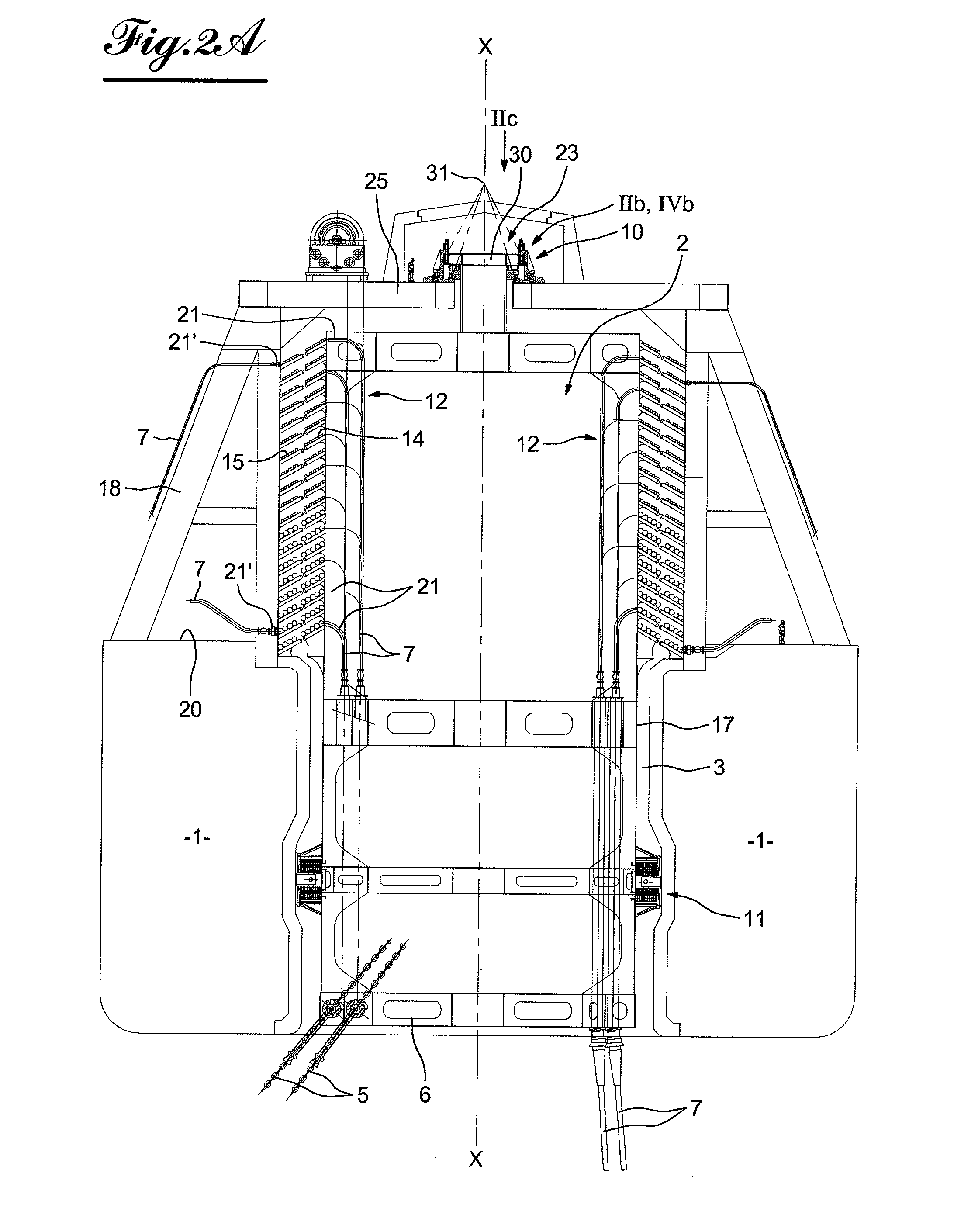
[0041]The invention concerns a facility such as illustrated in FIG. 1. This facility essentially comprises a floating unit 1 for the production, storage and unloading of fluid such as oil or gas, which is moored by a rotating, single-point mooring system via a turret 2 which is pivotally mounted in an opening in the form of a shaft 3 and passes fully and vertically through the floating unit. The turret is moored to the seafloor 4 via cables, chains, or any other suitable means 5 the other end of which is secured to the base 6 of the turret for example. The figure shows two fluid transfer pipes 7 among the large number provided for optimal drilling of oil or gas fields. The lower ends of these pipes descend towards well-heads not illustrated, whilst the upper part of the pipes passes through the turret 2 to convey the fluid via the rotating fluid transfer device 9 towards different items of equipment schematically illustrated by reference 8 of the floating unit.

[0042]The turret 2 is ...


PUM


Abstract

A facility for producing and processing fluids, including a boat with a system for rotatable single-point mooring via a turret pivotably mounted in a shaft which extends vertically through the hull of the boat. The turret includes an upper portion having a rotary device for receiving and supporting incoming fluid-transfer pipes, and an upper bearing, smaller in diameter than the shaft, positioned between a head portion of the upper portion of the turret and a supporting structure connected to the hull of the vessel. The upper bearing of the turret is located above the rotary device for receiving and supporting the incoming fluid-transfer pipes.

Description

FIELD OF THE INVENTION[0001]The invention concerns a facility in particular for producing and processing fluids, such as petroleum, of the type comprising a floating unit, such as a vessel provided with a rotating single-point mooring system formed by a turret pivotally mounted in an opening in the form of a shaft extending vertically through the hull of the floating unit moored to the seabed, and through which fluid-transfer pipes pass to transfer fluid to the equipment of the floating unit, the mooring system comprising devices guiding the turret in the shaft and which comprise axial and radial bearing means.BACKGROUND[0002]In facilities of this type, the axial bearing usually has a large diameter since it is arranged close to or on the edge of the shaft, and in the form of one or more axially superimposed rings around the pipes. The shaft may effectively be of large diameter when it is required to pass through the turret a large number of fluid-transfer pipes. However, the manufa...

Claims


Application Information

Patent Timeline
IPC IPC(8): B63B21/00B63B35/44
CPCF16C19/50B63B21/507F16C2326/00F16C2300/14F16C2326/30
Inventor DUPONT, BERNARDDECHIRON, CYRILLE
Owner TECH FRANCE SA
Why Eureka
Eureka Blog
Learn More