Hand Held Vacuum Cleaner

a vacuum cleaner and hand-held technology, which is applied in the field of hand-held vacuum cleaners, can solve the problems of troublesome removal of dust from the dust container, loss of suction efficiency, and large volume of the dust container for this type of vacuum cleaner, and achieve the effect of facilitating the emptying of the vacuum cleaner and avoiding too fast clogging of the filter

Active Publication Date: 2013-02-07
AB ELECTROLUX
View PDF0 Cites 13 Cited by
  • Summary
  • Abstract
  • Description
  • Claims
  • Application Information

AI Technical Summary

Benefits of technology

[0005]The purpose of this invention is to create an arrangement which eliminates a too fast clogging of the filter and which facilitates emptying of the vacuum cleaner at the vacuum cleaner types described above. This is achieved by means of a device having the characteristics mentioned in the claims.
[0007]In a second aspect, the present invention provides a vacuum cleaner having a housing, a motor-fan unit contained in the housing and having a motor-fan inlet opening, an air inlet passage, and a dust container selectively attachable to the housing. The dust container has a container air inlet adapted to be in fluid communication with the air inlet passage when the dust container is attached to the housing, a container air outlet located at a first end of the dust container and adapted to be in fluid communication with the motor-fan inlet opening when the dust container is attached to the housing, a filter positioned between the container air inlet and the container air outlet, a first emptying opening having a first cover associated therewith, and a second emptying opening having a second cover associated therewith. In this aspect, the dust container can be emptied through the first emptying opening without removing the dust container from the housing.

Problems solved by technology

Removal of the dust from the dust container is hence troublesome, dirty and time consuming.
It should in this connection be mentioned that the volume of the dust container for this type of vacuum cleaners is very limited and that the filter is rapidly clogged which means lost suction efficiency and that emptying has to be done with short intervals.
It is further known, see EP 914795, to provide a hand held vacuum cleaner of the type mentioned above with a large opening covered by a pivotable lid in order to facilitate emptying but since the dust usually gets stuck to the filter the dust can not be easily poured out of the opening.
Moreover since the conventional filter system is quickly clogged the suction efficiency is still not sufficient.
Of course this type of vacuum cleaners also has the same disadvantages as the hand held vacuum cleaner described above with respect to filter clogging and handling when being emptied.

Method used


Image

  • Hand Held Vacuum Cleaner
  • Hand Held Vacuum Cleaner
  • Hand Held Vacuum Cleaner

Examples


Embodiment Construction

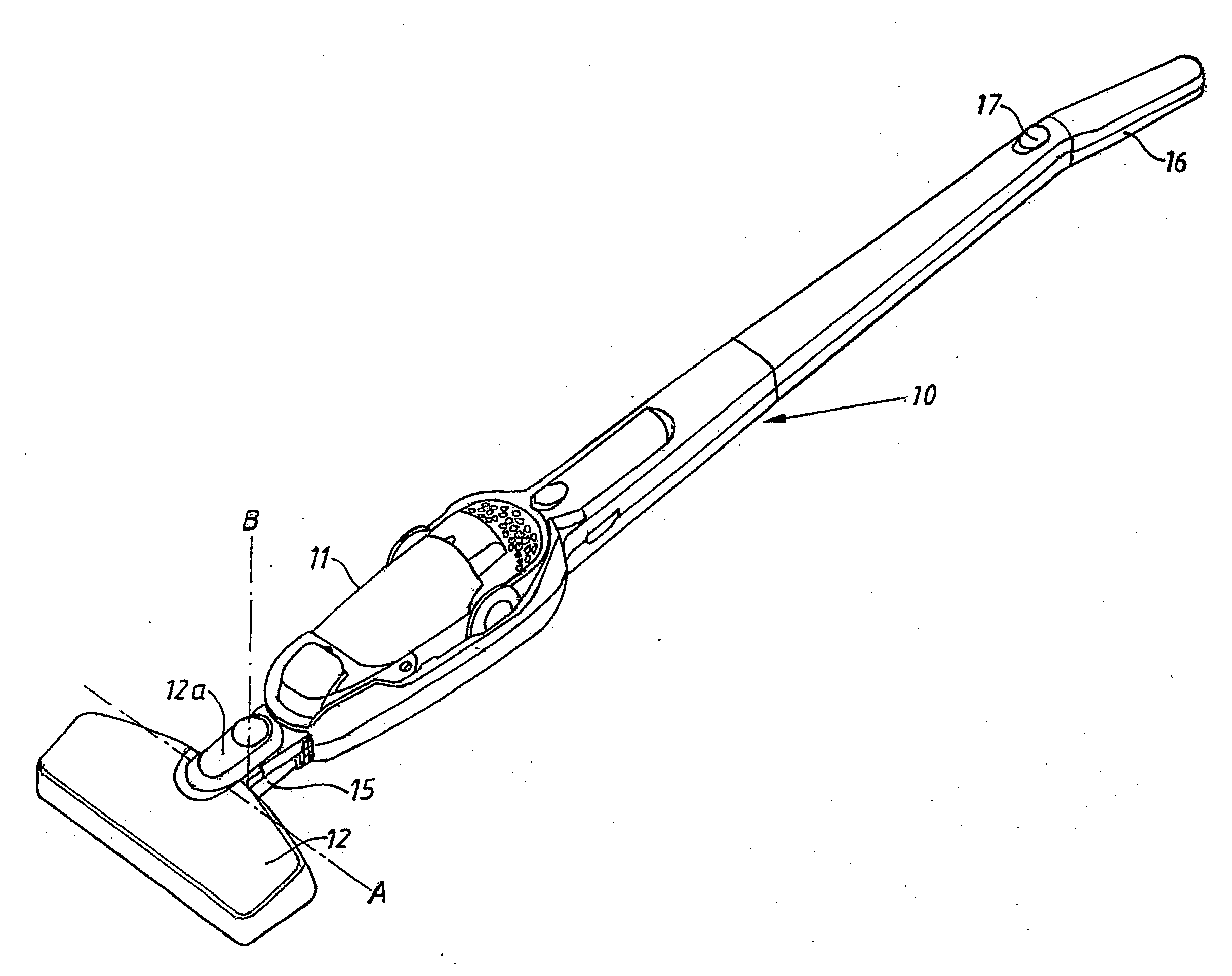
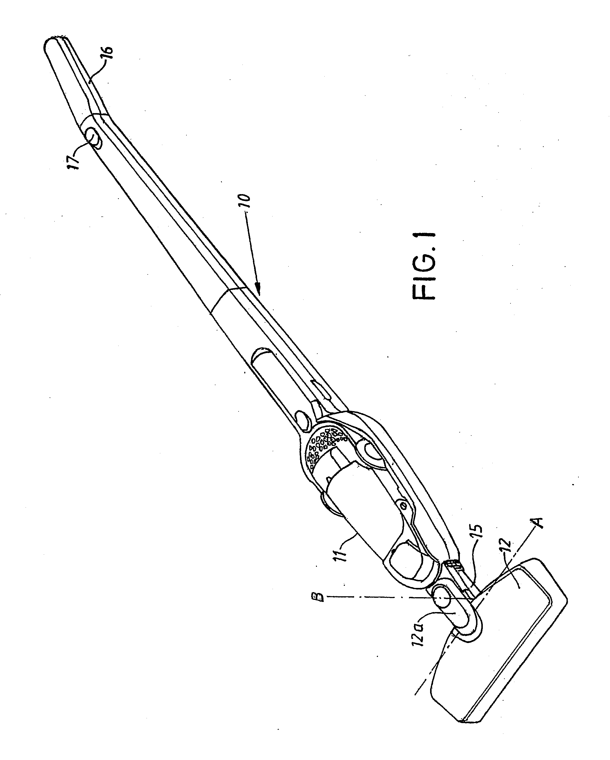
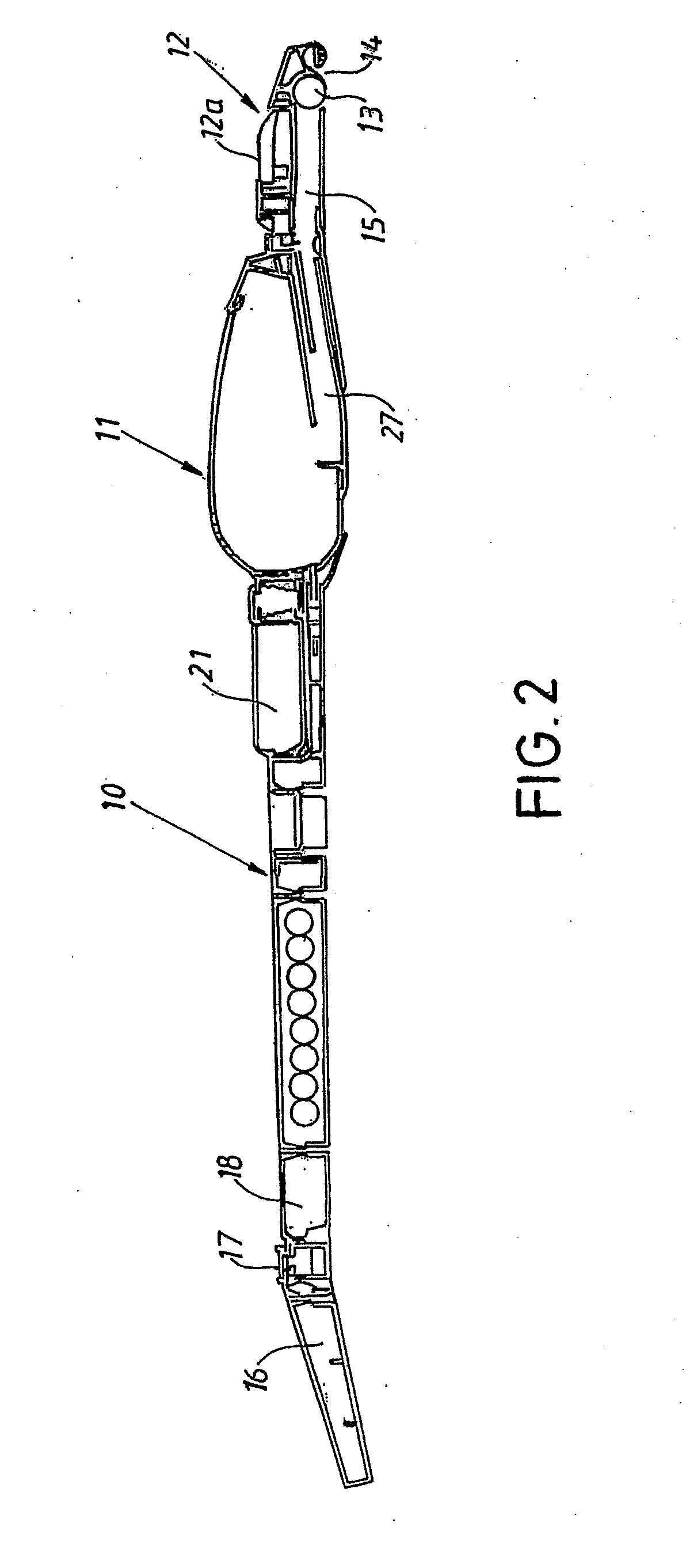
[0017]As appears from FIG. 1 the shown vacuum cleaner comprises an elongated shaft part 10 in which a hand held vacuum cleaner 11 is removably arranged. The lower end of the shaft part supports a floor nozzle 12 enclosing an electrically driven brush roll 13, not described in detail, and which is turnably secured to the shaft part 10. The nozzle has an elongated suction opening 14 extending in the length direction of the nozzle and the suction opening is via a flexible tube passage 15 connected to the hand held vacuum cleaner 11 in a manner which will be described below. The upper portion of the shaft part 10 is shaped as a handle 16 and has an operating knob 17 that via an electric circuit, not shown in detail, is connected to the hand held vacuum cleaner when it is secured to the shaft part. The shaft part might also enclose one or several batteries 18 which are connected to the electric circuit.

[0018]The nozzle 12 is provided with a supporting part 12a having one end that via a s...


PUM


Abstract

A vacuum cleaner apparatus for securing a hand held vacuum cleaner having a housing, the housing comprising a motor-fan unit, a dust container, and an air passage. The vacuum cleaner apparatus has a shaft part to which the housing can be secured, the shaft part comprising a handle and one or more batteries. The vacuum cleaner apparatus also has a floor nozzle and a tube passage configured to connect the floor nozzle to the air passage when the housing is secured to the shaft part.

Description

FIELD OF THE INVENTION[0001]This application is a continuation of U.S. application Ser. No. 10 / 544,927, filed Apr. 13, 2007, now U.S. Pat. No. 8,225,456, which was filed under 35 USC §371 of International Application No. PCT / SE2004 / 000136 filed Jan. 30, 2004 which claims priority to Swedish Application No. 0300355-5 filed on Feb. 10, 2003, the disclosure of each which is included herein by reference in its entirety. This invention relates to a hand held vacuum cleaner comprising a housing supporting a motor-fan unit, a dust container and an air passage ending in the dust container through which dust laden air is directed into the dust container, the vacuum cleaner also comprising at least one filter arranged after the dust container as seen in the flow direction, the dust container constituting a part of a cyclone separator arranged between the air passage and the filter.BACKGROUND[0002]Hand held vacuum cleaners which are battery powered as well as powered by mains supply, are previ...

Claims


Application Information

Patent Timeline
Patent Type & Authority Applications(United States)
IPC IPC(8): A47L5/24A47L5/28A47L9/16
CPCA47L5/225A47L5/24A47L5/28A47L9/244A47L9/1666A47L9/1683A47L9/106
Inventor MIEFALK, HAKANBERGLING, FREDRIKJONSSON, STEFANSVANTESSON, ESBJORNGREN, CHRISTIAN
Owner AB ELECTROLUX
Why Eureka
Try Eureka