
Ostial stent

a stent and ostial technology, applied in the field of stents, can solve the problems of difficult precise positioning of balloon-expandable stents, poor stent sensitivity, and various undesirable limitations of prior art stents, and achieve the effects of improving vessel patency in the ostial region, improving ostial region stent sensitivity, and simplifying and accurate placemen

Inactive Publication Date: 2013-01-31
CORRIGAN JR RICHARD F
View PDF14 Cites 2 Cited by
  • Summary
  • Abstract
  • Description
  • Claims
  • Application Information

AI Technical Summary

Benefits of technology

The present invention provides an ostial stent system that overcomes the limitations of prior art stents. The system includes a manually-expanding tube and a pre-shaped self-expanding SMA tube that are attached end-to-end to define a passage extending continuously between the openings. The self-expanding SMA tube is self-expandable from a radially contracted condition to a memory flared condition when heated by exposure to the body temperature of the patient. The method includes positioning the stent into a vessel of the patient and permitting the self-expanding SMA tube to self-expand to a flared condition by exposing the stent to the body temperature of the patient. The technical effects of the invention include improved vessel patency in the ostial region and simplified and accurate placement of the stent.

Problems solved by technology

Prior art stents suffer from various undesirable limitations.
Conventional stents are not well suited for precise placement in ostial regions of a patient's vascular system so as to conform to the ostial flaring of the larger vessel, particularly in the ostium region between the aorta and renal artery.
For instance, balloon-expandable stents are difficult to precisely position in such an ostial region because of artery movement due to beating of the heart and patient breathing.
Furthermore, precise positioning is difficult because such stents are slightly radiopaque and, therefore, can be difficult to view during positioning.
Even when properly positioned, it may be necessary to flare the proximal end of the stent with the balloon catheter, which can be difficult.
Self-expanding shape memory alloy (SMA) stents are deficient in some applications because such stents have less radial strength than balloon-expandable stents.

Method used


Image

  • Ostial stent
  • Ostial stent
  • Ostial stent

Examples


Embodiment Construction

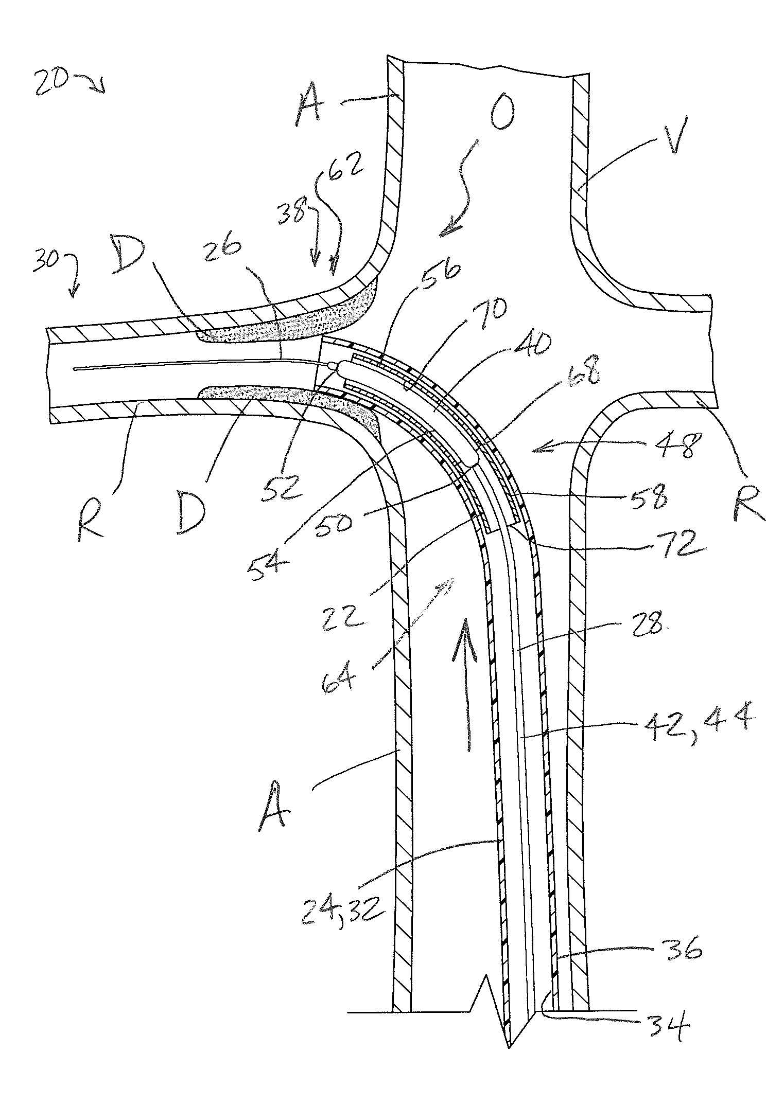
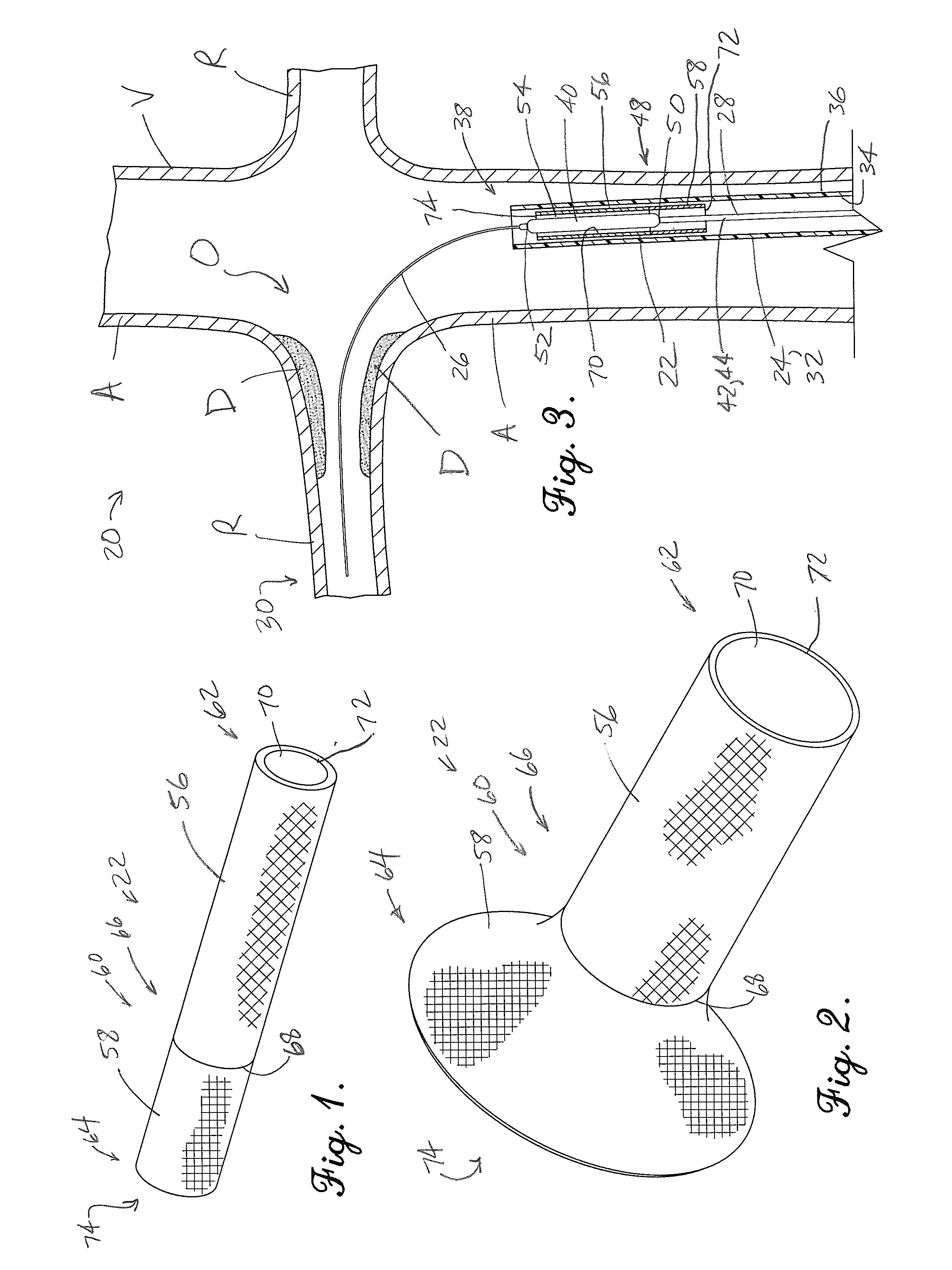
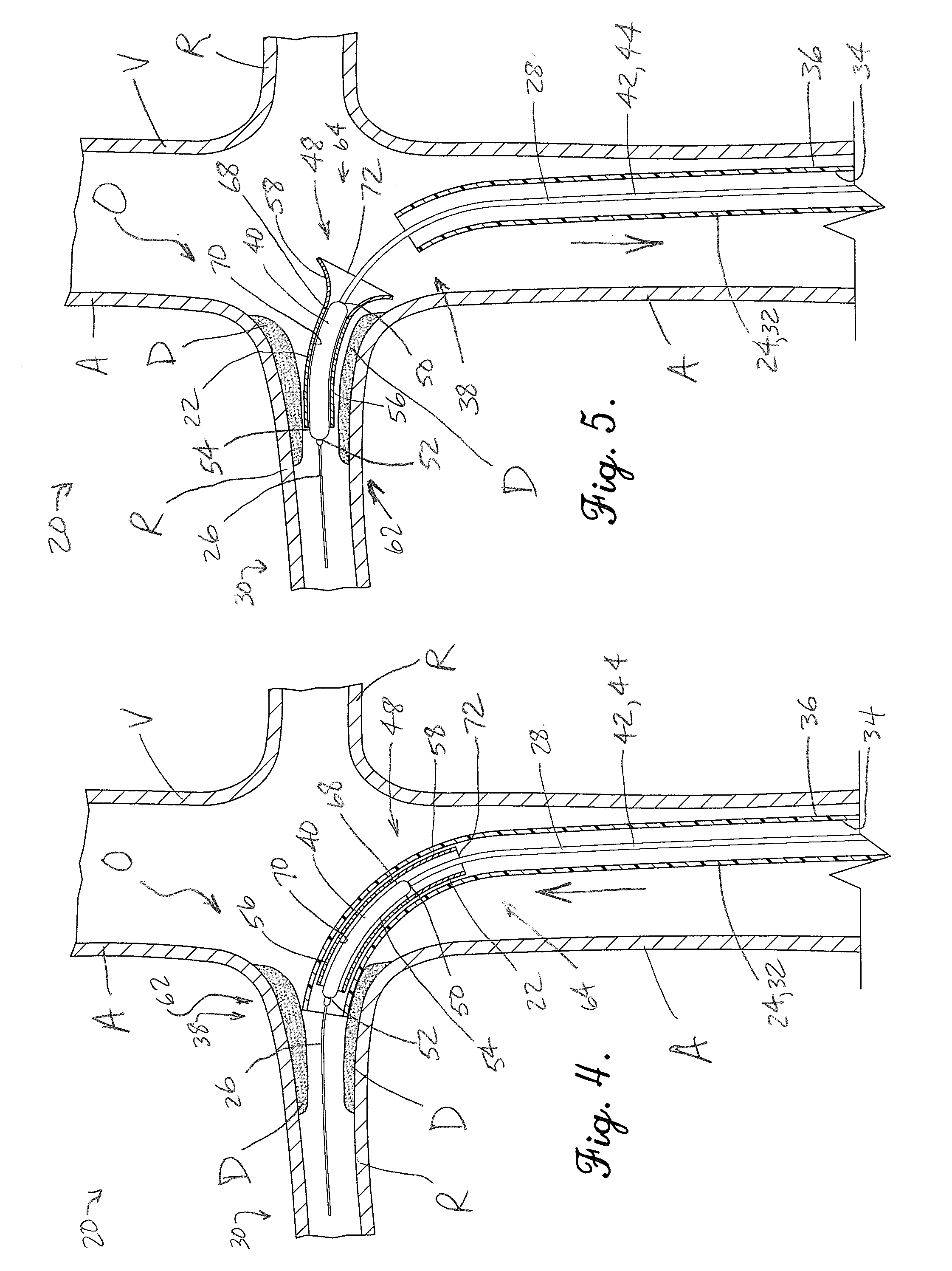
[0020]Turning initially to FIGS. 1, 2, and 3, an ostial stent system 20 is constructed in accordance with a preferred embodiment of the present invention. The ostial stent system 20 is preferably used to implant an ostial stent 22 in an ostial region O of a patient's vascular system and thereby improve vessel patency in the ostial region. As used herein, the term “ostial region” refers to a junction between two vessels. One such junction includes an ostium, which is normally the mouth of the smaller of the two vessels.

[0021]As will be discussed further, it has been found that the illustrated system 20 provides for simple and accurate stent implantation in the ostial region. More particularly, the system 20 restricts the operator from advancing the stent too far into the ostium. At the same time, the system 20 signals the operator that the stent has been sufficiently advanced into the ostium. The ostial stent system 20 broadly includes the ostial stent 22, a guide catheter 24, a guid...


PUM


Abstract

An ostial stent for use in improving vessel patency includes a manually-expanding tube section that presents a distal opening of the ostial stent and a pre-shaped self-expanding SMA tube that presents a proximal opening of the ostial stent. The tubes are attached end-to-end to define a passage extending continuously between the openings. The tubes have a generally cylindrical shape in a radially contracted condition so that the tubes can be inserted into the patient. The self-expanding SMA tube is self-expandable from the radially contracted condition to a memory flared condition.

Description

BACKGROUND[0001]1. Field[0002]The present invention relates generally to stents and methods of accurately placing and securing stents. More specifically, embodiments of the present invention concern an ostial stent with a manually-expanding distal tube section and a self-expanding proximal tube section.[0003]2. Discussion of Prior Art[0004]Stents have long been used to improve the patency of occluded vessels. In one conventional form, balloon-expandable stents are typically made of a relatively strong metal, such as stainless steel. This type of stent is used in vessels where greater radial strength is required. Furthermore, balloon-expandable stents are normally used in areas where the stent is unlikely to be crushed, e.g., by bending / crushing through contact with muscle or other tissues. In another conventional form, self-expanding stents are made of a relatively flexible shape memory alloy material. This type of stent is used where greater flexibility of the stent is required. Co...

Claims


Application Information

Patent Timeline
Patent Type & Authority Applications(United States)
IPC IPC(8): A61F2/84
CPCA61F2002/821A61F2/82
Inventor CORRIGAN, JR., RICHARD F.
Owner CORRIGAN JR RICHARD F
Learn More