
Anastomosis device

an anastomosis device and microvascular technology, applied in the field of microvascular anastomosis devices, can solve the problems of no clinical application developed for these two methods, no actual clinical application of these two methods, and long time-consuming, so as to reduce the damage of the vessel, avoid the collapse of the vessel wall, and shorten the operation time

Inactive Publication Date: 2011-05-05
NATIONAL YANG MING UNIVERSITY
View PDF22 Cites 9 Cited by
  • Summary
  • Abstract
  • Description
  • Claims
  • Application Information

AI Technical Summary

Benefits of technology

[0012]An objective of the present invention is to provide anastomosis devices capable of reducing the vessel damage during microvascular anastomosis, shortening the operation time, providing exterior support, and avoiding collapse of vessel wall so as to improve vessel patency while easy to be aligned and operated.

Problems solved by technology

It therefore may result in problems of taking long time, blood leakage from pinhole, or vessel occlusion due to the stitching of opposite side wall or twisting the blood vessels.
However, none of these two methods has any actual clinical applications developed due to their complicated and inconvenient operating procedure and the difficulty in maintaining a high patency.
However, because it is difficult to maintain the stress distribution in vessel walls uniformly, the vessel wall may be damaged easily by this method.
The “extraluminal cuffing ring” is a coupler using clamping as tissue holding mechanism, which does not have any commercialized products yet.
However, a common drawback of these methods was that the vessels have to be firstly everted for 90 degrees or even 180 degrees in operation, which is not applicable to the vessel wall with atherosclerotic change and may cause vessel spasm due to tension at the anastomosis site, the consequence of insufficient vessel length for eversion.
This drawback had substantially restricted the implementation of these methods in microvascular anastomosis.
Also, these ring-shaped anastomotic couplers required a complicated staple launcher or alignment equipment which makes the system expensive.
Furthermore, the anastomotic staple or ring-pin type anastomotic coupler fixed the tissue by piercing vessel walls, which inevitably damaged the vessel wall.
The adherence by tissue clips or extraluminal cuffing ring also may cause pressure necrosis of vessel walls.
Because of the distinct material properties of anastomotic couplers and vessel walls, it is possible to cause local compliance mismatch of the vessel wall, and subsequently disturbs the transmission of pulse waves in blood circulation.

Method used


Image

  • Anastomosis device
  • Anastomosis device
  • Anastomosis device

Examples


Embodiment Construction

[0029]Although the invention has been explained in relation to several preferred embodiments, the accompanying drawings and the following detailed description are the preferred embodiment of the present invention. It is to be understood that the following disclosed descriptions will be examples of present invention, and will not limit the present invention into the drawings and the special embodiment.

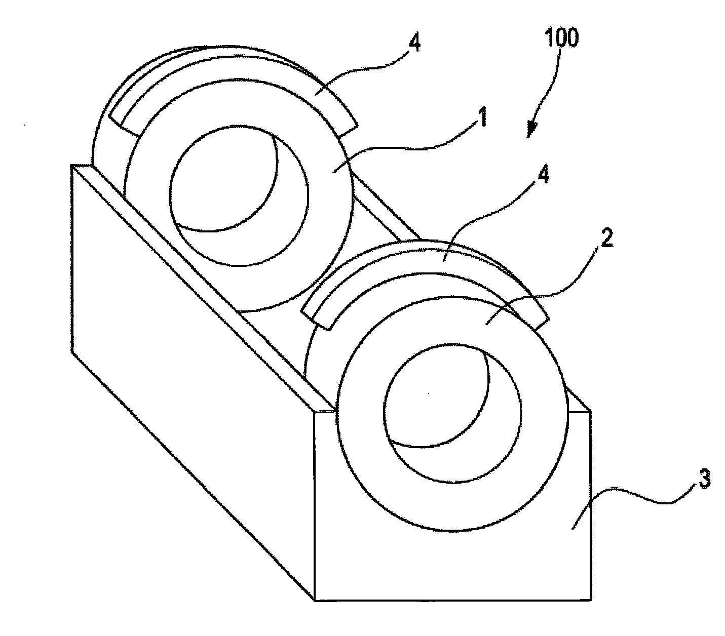
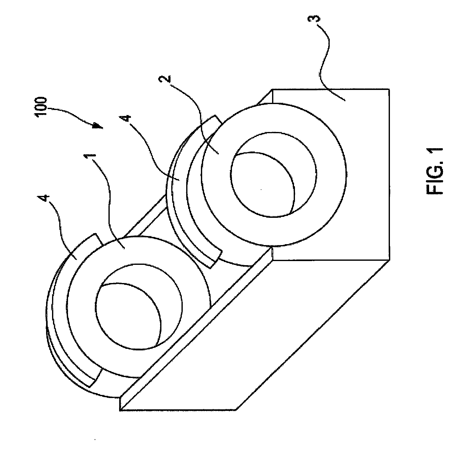
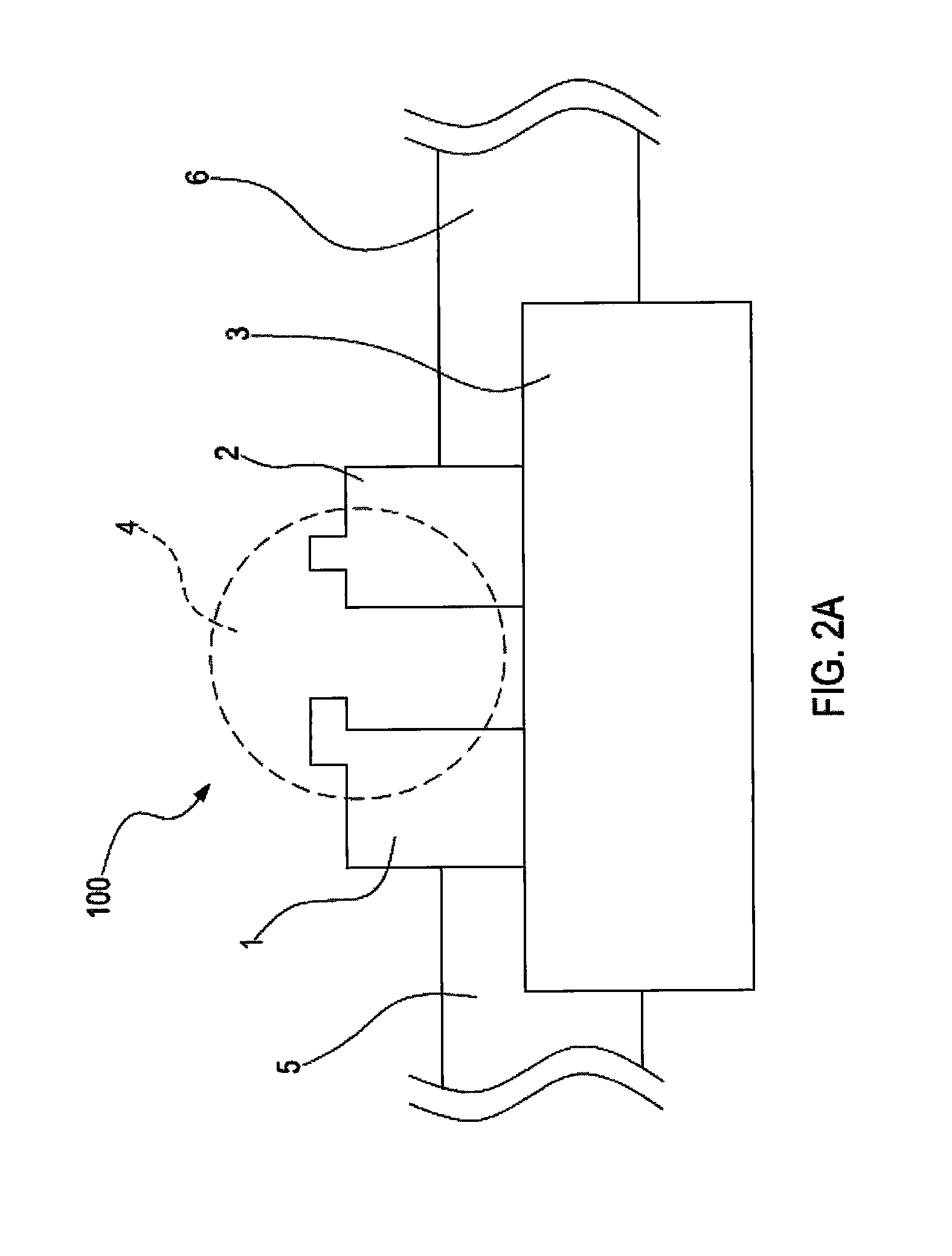
[0030]Please refer to FIG. 1, 2A and 2B, wherein FIG. 1 shows an assembly drawing of the anastomosis device in accordance with the invention, FIG. 2A shows a side view of the anastomosis device in accordance with the invention before linking two vessels, and FIG. 2B shows a side view of the anastomosis device in accordance with the invention while linking two vessels.

[0031]The anastomosis device 100 comprises a pair of ring bodies 1, 2 and a guiding base 3, wherein the ring bodies 1, 2 are two separated cylindrical ring-shaped members and have a tenon structure 4 with concave and convex...


PUM


Abstract

The present invention discloses an microvascular anastomosis device. The device comprises two rotatable and movable ring bodies disposed relatively on a guiding base, and a guiding member lead two vessels to pass through the two ring bodies respectively, wherein a tenon structure is disposed at the two ring bodies for aligning and embedding each other, and inner surface of each vessel is pressured in axial symmetry to make the outer surface of each vessel adhered and fixed onto the inner surface of each ring body, so as not to turn the vessels inside out when performing microvascular Anastomsis.

Description

BACKGROUND OF THE INVENTION[0001]1. Field of the Invention[0002]The present invention generally relates to an anastomosis device, and more particularly to an microvascular anastomosis device without turning the vessel wall inside out when operating.[0003]2. Description of the Related Art[0004]The anastomosis of blood vessel is one of the most important achievement in contemporary surgery which expands the surgical field to help patients getting better treatment results. Operations such as Heart Bypass Surgery, Solid-Organ Transplantation, Radiocephalic Fistula, Microvascular Free Flap Reconstruction, and etc. are all required to be finished up with anastomosis of blood vessels. As for Microvascular Free Flap Reconstruction, the anastomosis of blood vessel makes it possible for the patients with congenital anomalies, malignant tumor invasion, or injured-caused massive soft tissue defects to be able to receive autograft to resurface the defects, and then improve function and appearanc...

Claims


Application Information

Patent Timeline
Patent Type & Authority Applications(United States)
IPC IPC(8): A61B17/11
CPCA61B17/11A61B2017/1132A61B2017/1107
Inventor LIN, CHIH-HSUNTSAY, RUEY-YUG
Owner NATIONAL YANG MING UNIVERSITY
Learn More