Eccentricity measuring method
a measurement method and eccentricity technology, applied in the direction of measurement devices, geometric properties/aberration measurement, instruments, etc., can solve the problems of prolonged measurement preparation period and inflated facility cos
- Summary
- Abstract
- Description
- Claims
- Application Information
AI Technical Summary
Benefits of technology
Problems solved by technology
Method used
Image
Examples
first embodiment
[0051]In FIG. 4, an eccentricity measurement method comprises the five steps below.
[0052](S1) First Flange Surface Adjusting Step
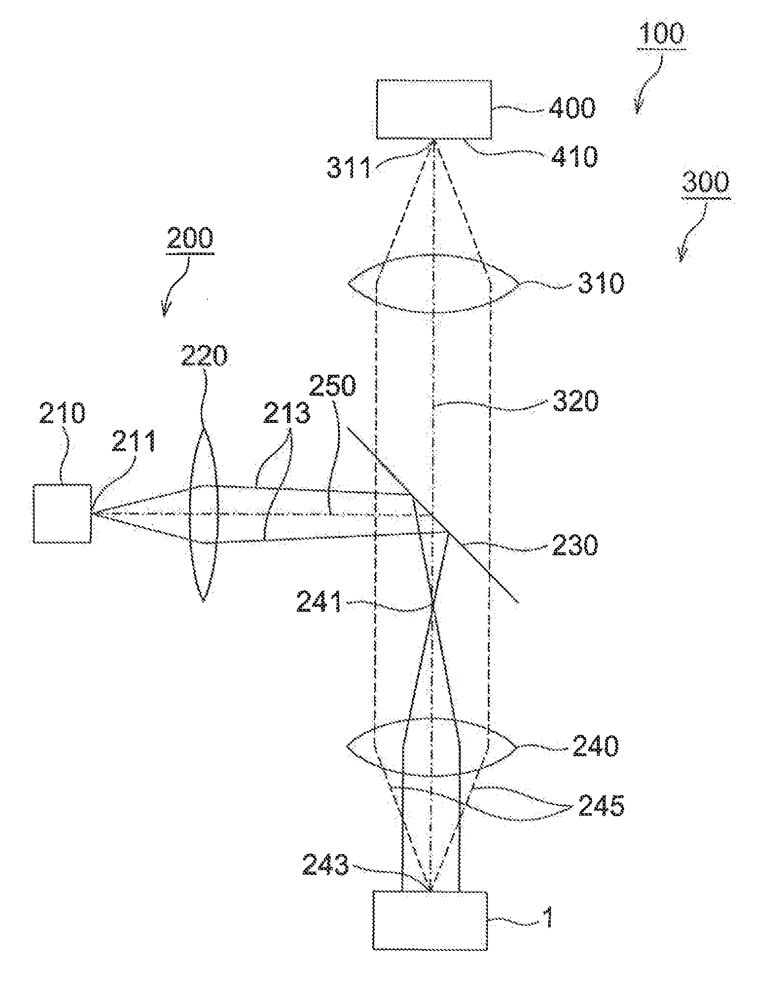
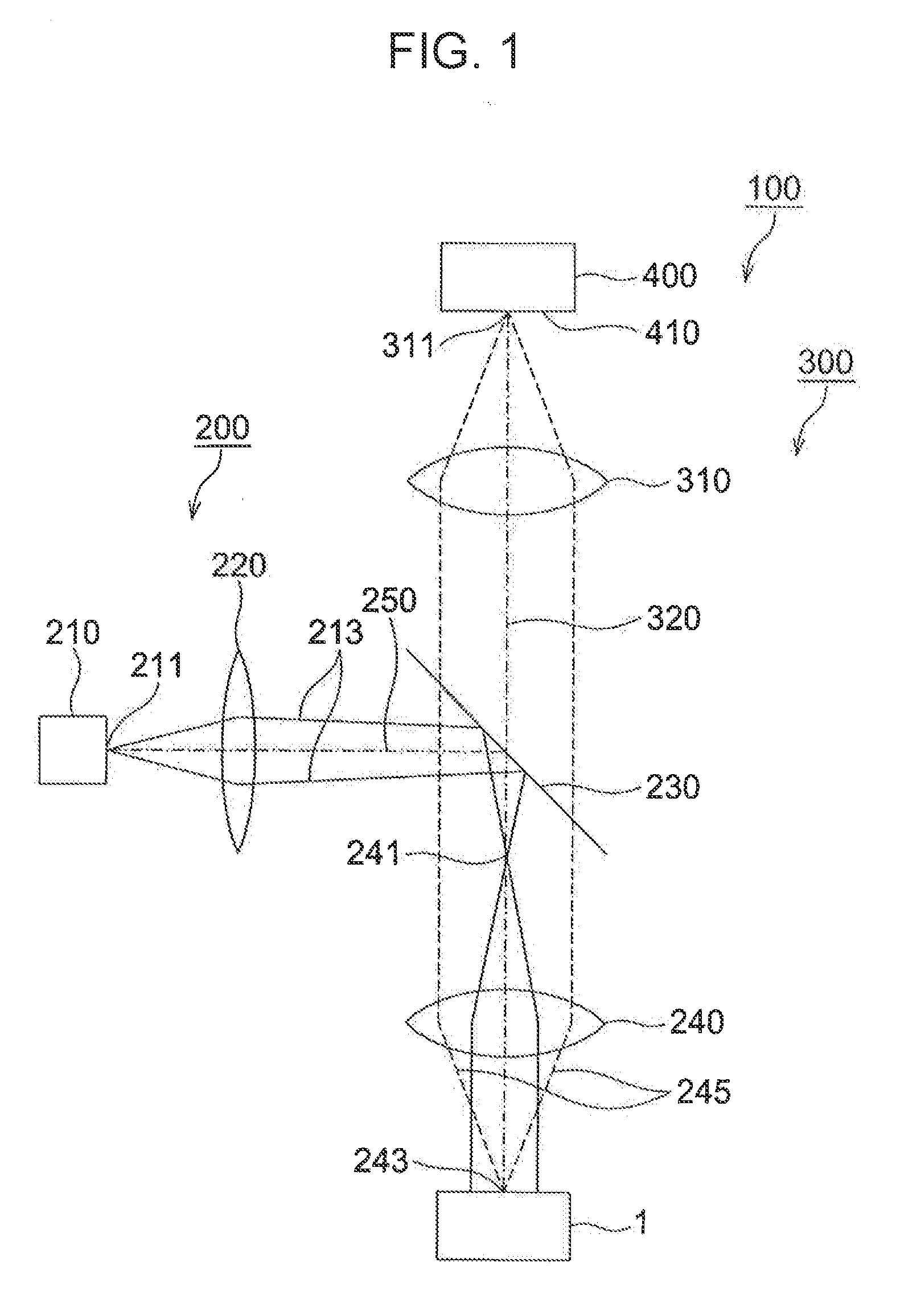
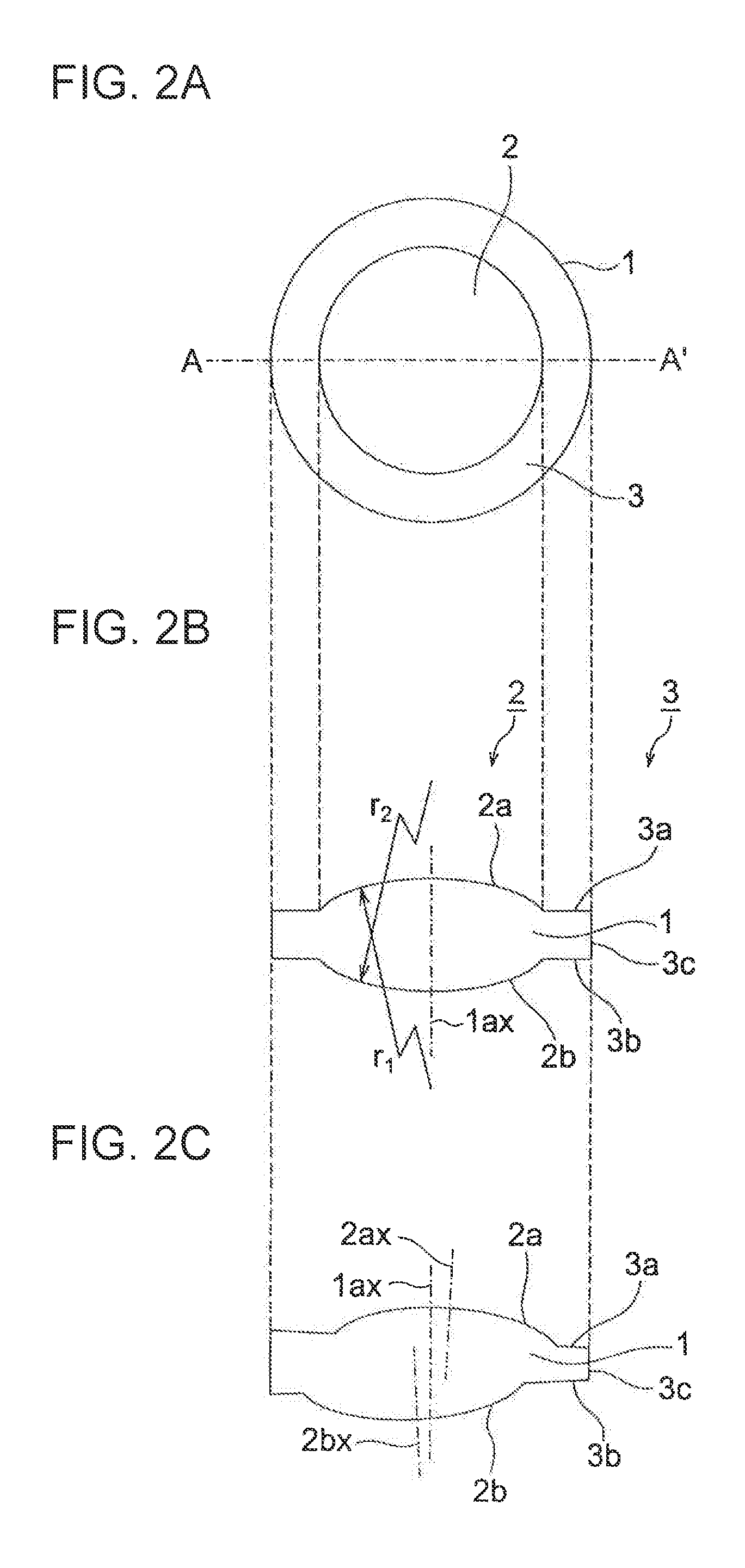
[0053]This first flange surface adjusting step is a step in which the first flange surface 3a is adjusted so as to be perpendicular to the optical axis 320 of the eccentricity measuring device 100 in order to correct eccentricity caused by a posture error attributable to an inclination of the lens 1. As shown in FIG. 5A, the lens 1 is held by a holding section 500 so that, for example, with reference to the second flange surface 3b and the lens end surface 3c of the flange portion 3, the lens 1 is rotatable around the optical axis 320 and, at the same time, the lens 1 is movable parallel to the optical axis 320.
[0054]In step S11 in FIG. 4, the parallel illuminating light 213 is inputted to the lens 1. In step S12, a lens which is referred to as an interference objective lens and which enables an inclination of a surface to be ascertained based on interfere...
second embodiment
[0075]In FIG. 9, an eccentricity measurement method comprises the five steps below.
[0076](S1) First Flange Surface Adjusting Step
[0077]The first flange surface adjusting step is a step in which the first flange surface 3a is adjusted so as to be perpendicular to an optical axis 320 of an eccentricity measuring device 100. Since this step is the same as (S1) first flange surface adjusting step according to the first embodiment and shown in FIGS. 4 and 5A, a description thereof will be omitted.
[0078](S6) Center Mark Position Measuring Step
[0079]The center mark position measuring step is a step in which a position of the center mark 2c provided on the first optical surface 2a is measured. In step S61 in FIG. 9, as shown in FIG. 10A, an interval between an objective lens 240 and the lens 1 is changed so that a focal point 243 of the objective lens 240 is brought into focus on the center mark 2c provided on the first optical surface 2a. Accordingly, an image of the center mark 2c is form...
third embodiment
[0096]In FIG. 13, an eccentricity measurement method comprises the five steps below.
[0097](S1) First Flange Surface Adjusting Step
[0098]The first flange surface adjusting step is a step in which the first flange surface 3a is adjusted so as to be perpendicular to an optical axis 320 of an eccentricity measuring device 100. Since this step is the same as (S1) first flange surface adjusting step according to the first embodiment and shown in FIGS. 4 and 5A, a description thereof will be omitted.
[0099](S7) Alignment Mark Position Measuring Step
[0100]The alignment mark position measuring step is a step in which a position of the alignment mark 4 provided on the first flange surface 3a is measured, In step S71 in FIG. 13, the lens array 10 is scanned within an x-y plane shown in FIG. 12 and, at the same time, a focal point 243 of an objective lens 240 is brought into focus on the alignment mark 4. In step S72, a position of an image of the alignment mark 4 formed on an imaging plane 410 ...
PUM
 Abstract
Description
Claims
Application Information
 - R&D
- Intellectual Property
- Life Sciences
- Materials
- Tech Scout
- Unparalleled Data Quality
- Higher Quality Content
- 60% Fewer Hallucinations
Browse by: Latest US Patents, China's latest patents, Technical Efficacy Thesaurus, Application Domain, Technology Topic, Popular Technical Reports.
© 2025 PatSnap. All rights reserved.Legal|Privacy policy|Modern Slavery Act Transparency Statement|Sitemap|About US| Contact US: help@patsnap.com


