
Process for stabilization of heavy hydrocarbons

Active Publication Date: 2013-01-31
SAUDI ARABIAN OIL CO
View PDF2 Cites 39 Cited by
  • Summary
  • Abstract
  • Description
  • Claims
  • Application Information

AI Technical Summary

Benefits of technology

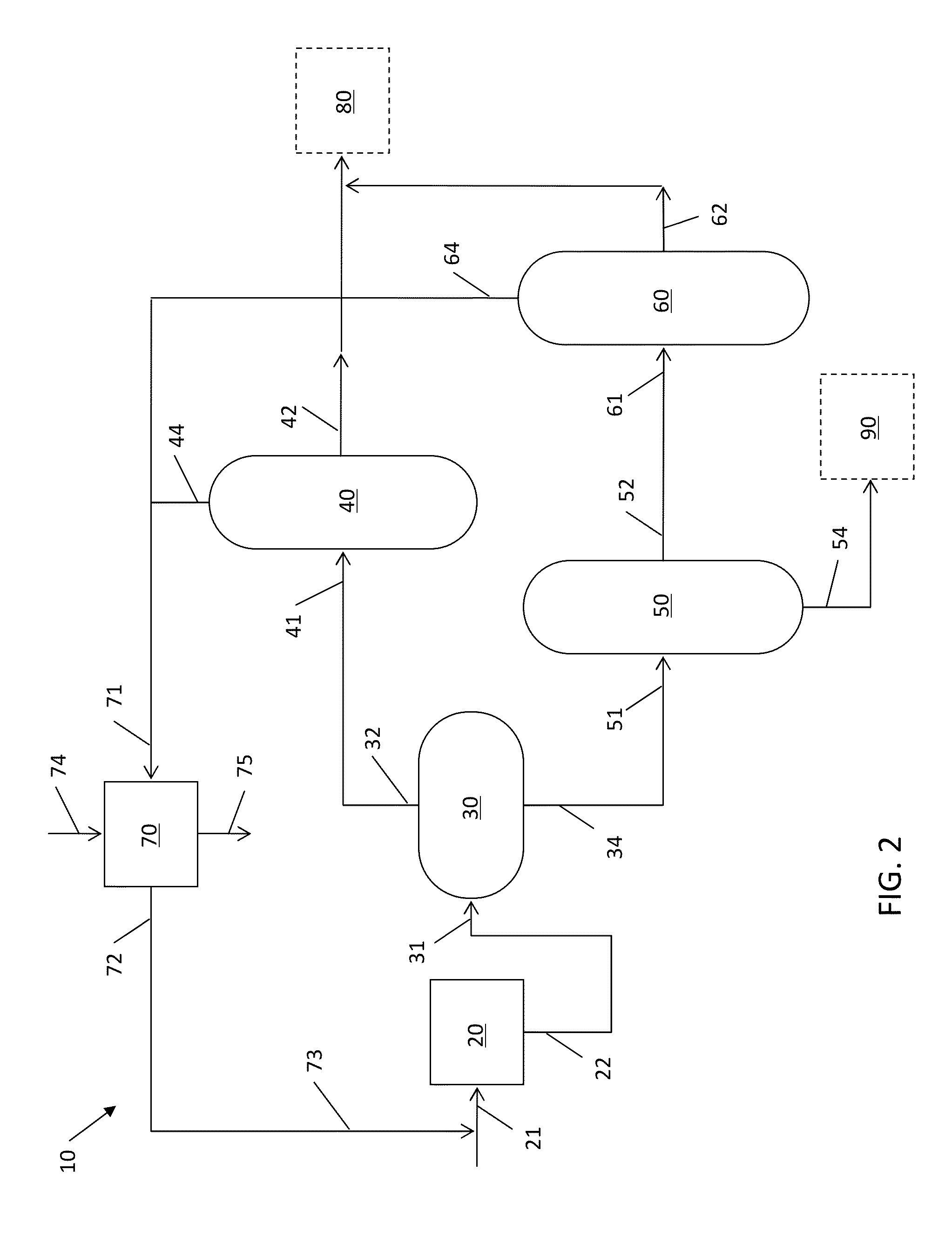
The patent text describes a process for removing sediment precursors and preventing further sediment formation using high carbon number paraffinic or heavy naphtha solvents. This process reduces sludge formation and minimizes yield loss. The low temperature and pressure operating conditions allow for the addition of equipment at a low cost, and a wide range of contact vessels can be used.

Problems solved by technology

Vacuum residues can also contain metals such as nickel and vanadium which make them difficult to process, since they deactivate or poison the catalysts used.
It is also known that the amount of asphaltenes decreases with an increase in the carbon number of the solvent used to separate the asphaltenes, but with a loss in the quality of the treated oil.
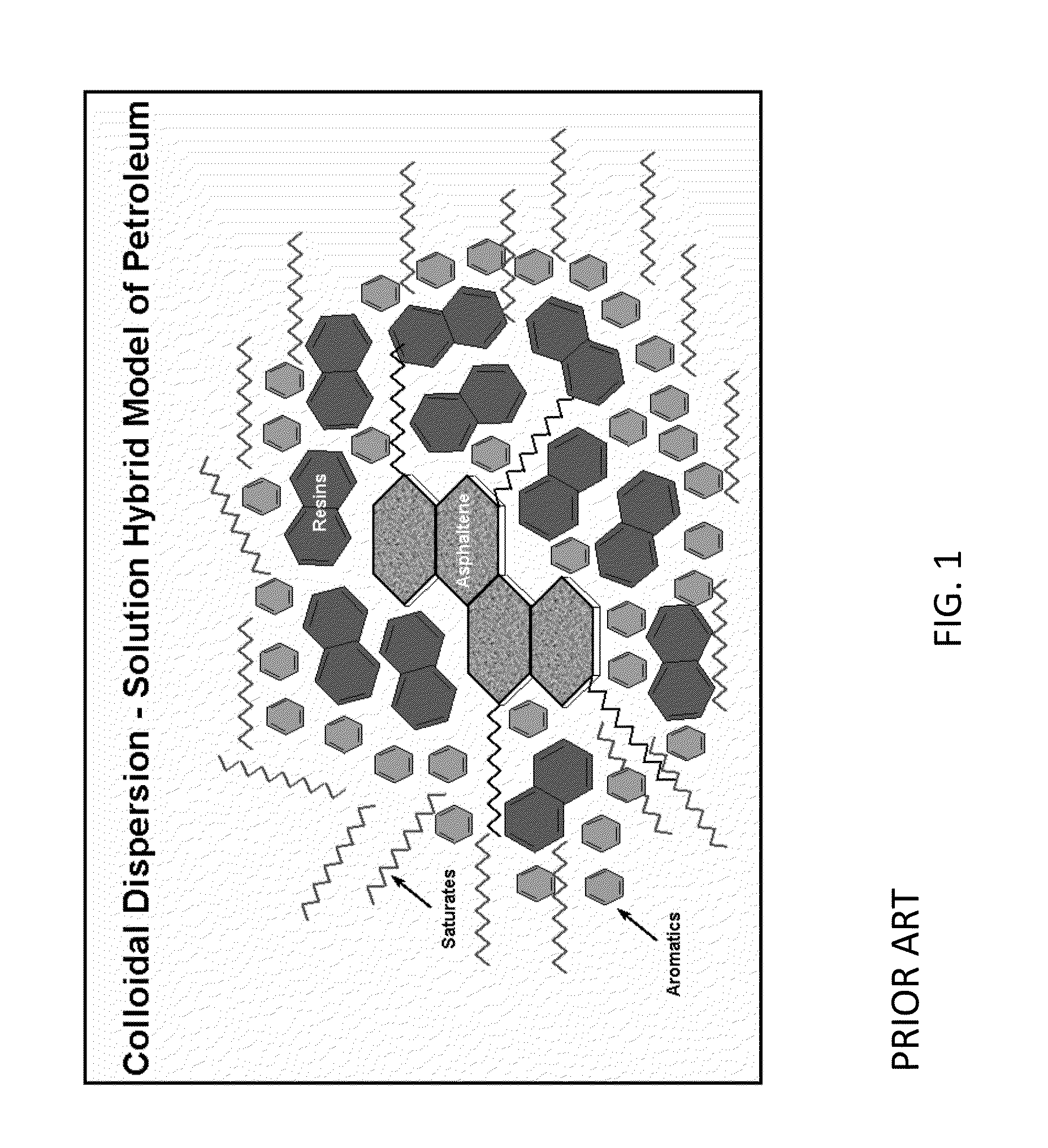
The accumulated precipitate of asphaltenes form a hard sediment, also referred to as “sludge.” The technical problems created by sludge formation include blockage of pipelines and burner nozzles, reduction in storage capacity, pump malfunctions, corrosion, false measurements and plugging.
Routine industrial maintenance of storage tanks unavoidably means the temporary inoperability of equipment.
Furthermore, when conventional treatments are used to remove sludge, there is a potential for a significant negative environmental impact.
While the solvent deasphalting process can be effective in removing almost all of the asphaltenes from the feedstock and thereby reduce sludge formation, a large portion of feedstock is rejected as asphalt due to the nature of the low carbon number paraffinic solvent used, resulting in a large loss in yield.

Method used


Image

  • Process for stabilization of heavy hydrocarbons
  • Process for stabilization of heavy hydrocarbons

Examples


example 1

[0050]A hydrocarbon sample having an initial boiling point of 560° C., the properties of which are given in Table 2, was mixed with hexadecane at a 1:1 ratio by volume and maintained at 100° C. and atmospheric pressure for one hour. The combined product was filtered through a sintered glass filter having a 145 to 175 micron pore size, and 0.1 W % of asphaltenes were recovered.

TABLE 2Sulfur1.3W %Hydrogen10.0W %Nitrogen4,000ppmwConradson Carbon Residue29W %Pentane Asphaltenes6W %Aromatics60W %

example 2

[0051]A hydrocarbon sample having an initial boiling point of 290° C., the properties of which are given in Table 3, was mixed with hexadecane at a 1:1 ratio by volume and maintained at 100° C. and atmospheric pressure for one hour. The combined product was filtered through a sintered glass filter having 145 to 175 micron pore size, and 0.4 W % of asphaltenes were recovered.

TABLE 3Sulfur1.5W %Hydrogen11.2W %Nitrogen2,200ppmwConradson Carbon Residue15W %Pentane Asphaltenes3W %Aromatics48W %

example 3

[0052]A hydrocarbon sample having an initial boiling point of 210° C., the properties of which are given in Table 4, was mixed with hexadecane at a 1:1 ratio by volume and maintained at 100° C. and atmospheric pressure for 1 hour. The combined product was filtered through a sintered glass filter having 145 to 175 micron pore size, and 0.5 W % of asphaltenes were recovered.

TABLE 4Sulfur1.0W %Hydrogen10.7W %Nitrogen2,000ppmwConradson Carbon Residue15W %Pentane Asphaltenes3W %Aromatics44W %


PUM


Abstract

A process for stabilization of heavy hydrocarbons to reduce sludge formation in storage tanks and / or transportation lines and to enhance the hydrocarbon yield includes mixing a paraffinic or heavy naphtha solvent having carbon numbers in the range 10 to 20 with the feedstock to solvent-flocculate a relatively small, predetermined portion of asphaltenes present in the feedstock, separating and flashing the sediment to recover a light hydrocarbon fraction, flashing the heavy hydrocarbon / solvent phase and recycling the solvent to stabilize the heavy hydrocarbons without significantly affecting the yield of valuable products.

Description

RELATED APPLICATIONS[0001]This application claims priority to provisional patent application U.S. Ser. No. 61 / 513,457 filed Jul. 29, 2011, the contents of which are incorporated herein by reference.BACKGROUND OF THE INVENTION[0002]1. Field of the Invention[0003]The present invention relates to a process for stabilization of heavy hydrocarbons by efficiently preventing sludge formation in storage tanks and / or transportation lines.[0004]2. Description of Related Art[0005]The composition of crude oils and their heavy hydrocarbon fractions varies greatly depending upon their geographic origins and types. Properties of several sample vacuum residues derived from various crude oils are shown in Table 1. As can be seen from Table 1, vacuum residues can have a sulfur content that ranges from 0.2 to 7.7 W % and a nitrogen content that ranges from 3800 to 7800 parts per million by weight (ppmw). Vacuum residues can also contain metals such as nickel and vanadium which make them difficult to p...

Claims


Application Information

Patent Timeline
IPC IPC(8): C10C3/08
CPCC10G31/06C10G1/002C10G21/28C10G21/003C10G21/14C10G2300/107C10G2300/1077C10G2300/206C10G2300/4075C10G2300/44
Inventor KOSEOGLU, OMER REFAAL-HAJJI, ADNAN
Owner SAUDI ARABIAN OIL CO
Learn More