Radiation generating apparatus and radiation imaging apparatus

a radiation generating apparatus and radiation imaging technology, applied in the direction of instruments, x-ray tubes, material analysis using wave/particle radiation, etc., can solve the problems of suppressing the withstand voltage performance at the opening of the insulating member, and reducing the radiation amount, reducing and improving the withstand voltage performan

Inactive Publication Date: 2013-01-17
CANON KK
View PDF6 Cites 19 Cited by
  • Summary
  • Abstract
  • Description
  • Claims
  • Application Information

AI Technical Summary

Benefits of technology

[0010]According to the present invention, the first window which is provided on the envelope in which the insulating liquid has been filled and the second window which is provided on the radiation tube which is arranged within the envelope are arranged so as to face each other, and the insulating member is arranged between the shielding member which has the radiation passing hole which is in communication with the second window and the inner wall of the envelope. Here, since the insulating member has the opening of the insulating member at the position corresponding to the first window, it is possible to prevent that the radiations which are emitted from the radiation tube are absorbed by the insulating member and thus the amount of the radiations is reduced. Further, since the solid insulating member is provided, the withstand voltage performance is improved at the opening of the insulating member. Furthermore, since the shortest length of the supposed strait line stretching from the shielding member to the first window or the inner wall of the envelope through the opening of the insulating member without intersecting the insulating member is made longer than the shortest length of the supposed strait line stretching from the shielding member to the first window or the inner wall of the envelope as intersecting the insulating member, it is possible to suppress that the withstand voltage performance at the opening of the insulating member is deteriorated. Thus, the withstand voltage performance between the radiation tube and the envelope can be secured even if the distance between the shielding member and the envelope is shortened, whereby it is possible to achieve reduction of size and weight of the apparatus.

Problems solved by technology

Furthermore, since the shortest length of the supposed strait line stretching from the shielding member to the first window or the inner wall of the envelope through the opening of the insulating member without intersecting the insulating member is made longer than the shortest length of the supposed strait line stretching from the shielding member to the first window or the inner wall of the envelope as intersecting the insulating member, it is possible to suppress that the withstand voltage performance at the opening of the insulating member is deteriorated.

Method used


Image

  • Radiation generating apparatus and radiation imaging apparatus
  • Radiation generating apparatus and radiation imaging apparatus
  • Radiation generating apparatus and radiation imaging apparatus

Examples


first embodiment

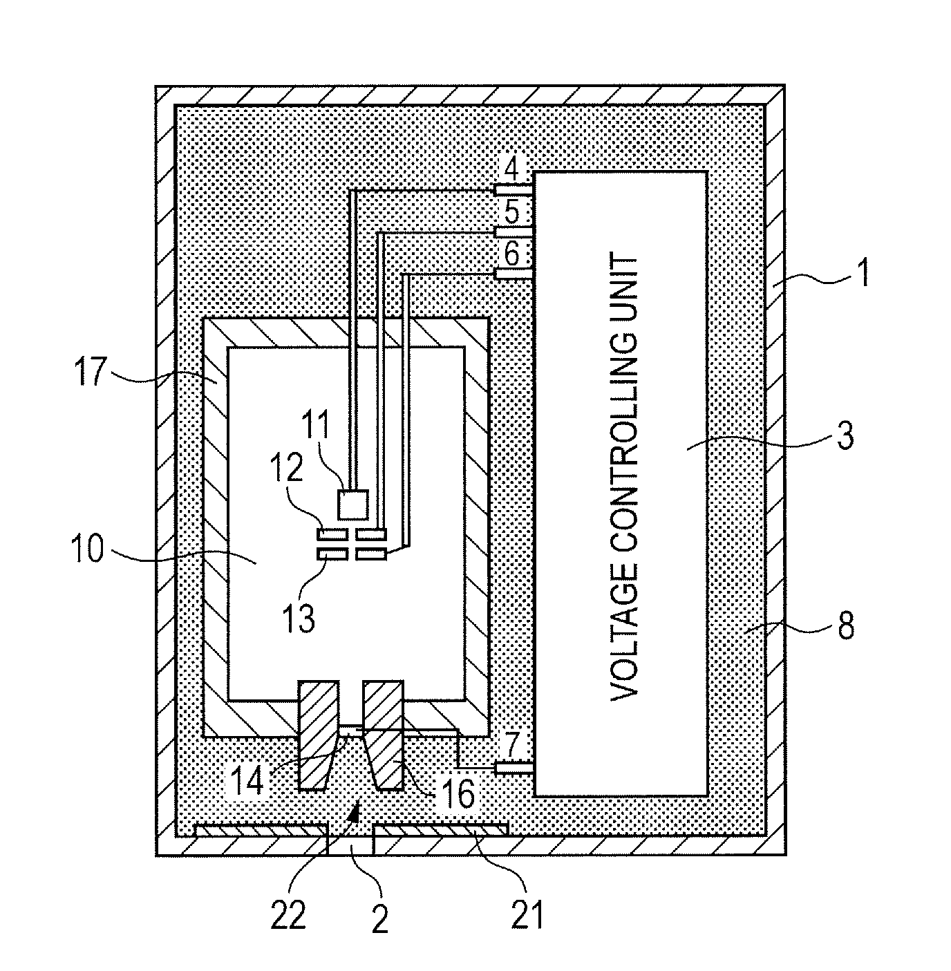
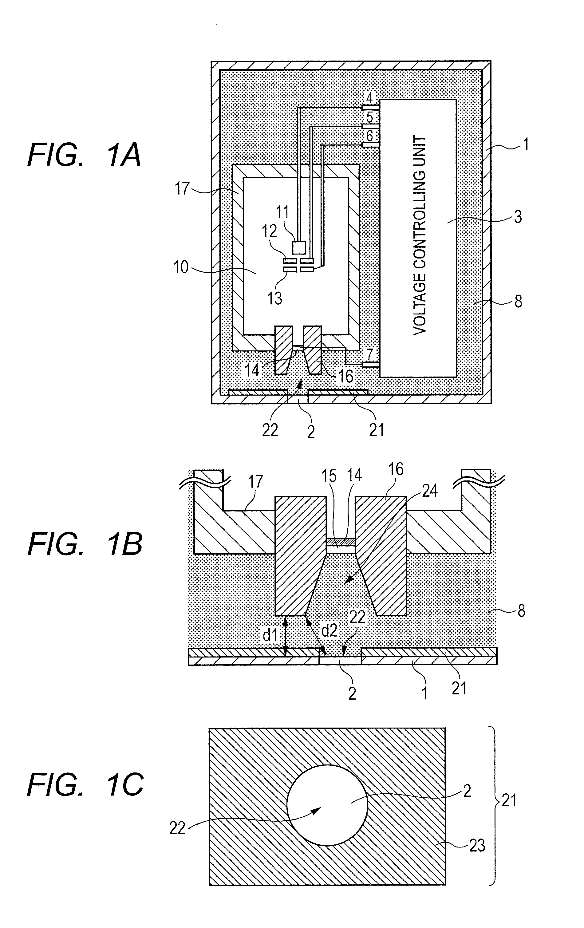
[0017]First of all, the first embodiment of the present invention will be described with reference to FIGS. 1A, 1B and 1C. More specifically, FIG. 1A is the cross-section schematic diagram illustrating a radiation generating apparatus according to the present embodiment, FIG. 1B is the enlarged cross-section schematic diagram illustrating a peripheral part of a radiation shielding member (called a shielding member, hereinafter) 16 and an insulating member both illustrated in FIG. 1A, and FIG. 1C is the schematic diagram of the insulating member 21 and a first window 2 for transmitting a radiation which are viewed from the side of the shielding member 16 all illustrated in FIG. 1A.

[0018]The radiation generating apparatus according to the present embodiment is equipped with a transmission-type radiation tube (called a radiation tube, hereinafter) 10, and the radiation tube 10 is held within an envelope 1.

[0019]Here, the radiation tube 10 includes a vacuum container 17, an electron emi...

second embodiment

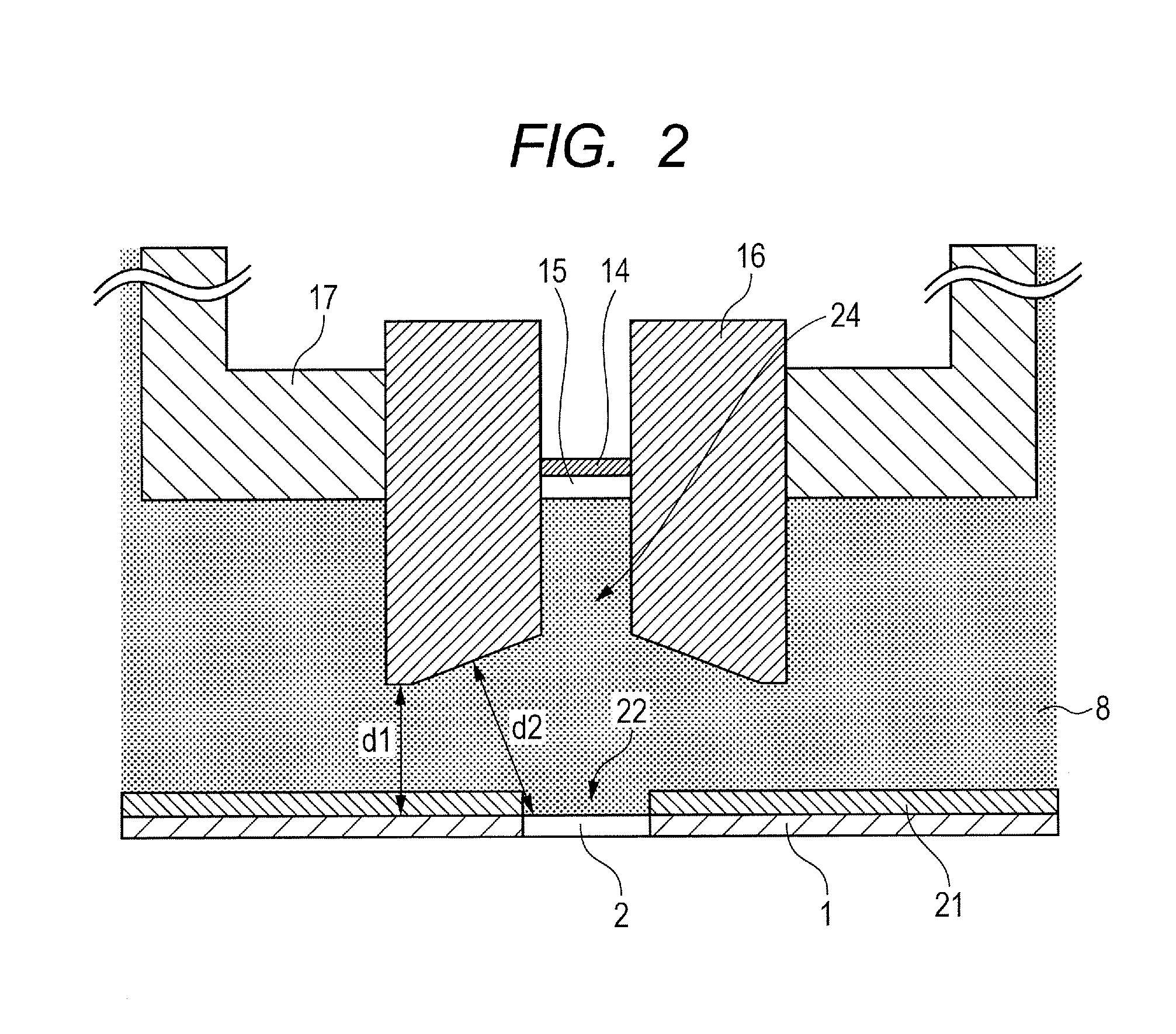
[0038]In the present invention, the shape of the shielding member 16 is not limited to that illustrated in FIGS. 1A to 1C. Namely, another shape may be used as the shape of the shielding member.

[0039]Therefore, another example of the shape of the shielding member 16 which can be adopted in the present invention will be described with reference to FIG. 2. That is, FIG. 2 is the cross-section schematic diagram illustrating the enlarged peripheral part of the shielding member 16 and the insulating member 21 in the radiation generating apparatus according to the second embodiment of the present invention. It should be noted that, in the present embodiment, the constituent parts other than the shielding member 16 are the same as those already described in the first embodiment.

[0040]The present embodiment is characterized in that the opening area of the radiation passing hole 24 of the shielding member 16 becomes gradually large from the middle of the radiation passing hole 24 toward the ...

third embodiment

[0043]In the present invention, the shape of the insulating member 21 is not limited to that illustrated in FIGS. 1A to 1C

[0044]Therefore, another example of the shape of the insulating member 21 which can be adopted in the present invention will be described with reference to FIGS. 3A and 3B. That is, FIG. 3A is the cross-section schematic diagram illustrating the enlarged peripheral part of the shielding member 16 and the insulating member 21 in the radiation generating apparatus according to the third embodiment of the present invention, and FIG. 3B is the schematic diagram of the insulating member 21 and the first window 2 which are viewed from the side of the shielding member 16 all illustrated in FIG. 3A. It should be noted that, in the present embodiment, the constituent parts other than the insulating member 21 are the same as those already described in the first embodiment.

[0045]The present embodiment is characterized in that the opening 22 of the insulating member 21 is fo...


PUM

PropertyMeasurementUnit
voltageaaaaaaaaaa
thicknessaaaaaaaaaa
thicknessaaaaaaaaaa

Abstract

In a radiation imaging apparatus which comprises an envelope which has a first window for transmitting a radiation and is filled with an insulating liquid, a radiation tube in the envelope which has, at a position facing the first window, a second window for transmitting the radiation, and a shielding member, a solid insulating member is arranged between the shielding member and the inner wall of the envelope, an opening is formed at a position on the insulating member corresponding to the first window, and a shortest distance from the shielding member to the first window or the inner wall of the envelope through the opening of the insulating member without the insulating member is made longer than a shortest distance from the shielding member to the first window or the inner wall of the envelope through the insulating member, thereby improving withstand voltage performance without reducing an radiation amount.

Description

FIELD OF THE INVENTION[0001]The present invention relates to a radiation generating apparatus which is applicable to a non-destructive X-ray photography or the like in the fields of medical equipment and industrial equipment, and a radiation imaging apparatus in which the radiation generating apparatus is used.DESCRIPTION OF THE RELATED ART[0002]In general, a radiation tube accelerates, at a high voltage, electrons emitted from an electron emitting source, and then irradiates the accelerated electrons to a target, thereby generating a radiation such as an X-ray or the like. At this time, the radiations are generated in all directions. In the circumstances, a transmission-type radiation tube in which shielding members are arranged on an electron incident side of a target and a radiation emitting side has been proposed to shield redundant radiations (Japanese Patent Application Laid-Open No. 2007-265981). In the radiation tube like this, it is unnecessary to cover, by a shielding memb...

Claims


Application Information

Patent Timeline
Patent Type & Authority Applications(United States)
IPC IPC(8): H01J35/18H05G1/32G01N23/04
CPCH01J35/12H01J35/14H01J35/16H01J35/18H01J2235/06H01J2235/087H05G1/06H01J2235/1216H01J2235/122H01J2235/1295H01J2235/16H01J2235/167H01J35/08H01J2235/1204H01J35/116H01J35/186
Inventor TAMURA, MIKIAOKI, SHUJIYANAGISAWA, YOSHIHIROUEDA, KAZUYUKI
Owner CANON KK
Why Eureka
Try Eureka