
Noise-reducing directional microphone array

a microphone array and noise reduction technology, applied in the field of acoustics, can solve the problems of limiting communication quality, wind noise is now becoming a major issue for users of directional hearing aids, and the sensitivity of microphones has been a major problem, so as to achieve the effect of increasing the amount of wind noise suppression and increasing the wind noise condition

Active Publication Date: 2013-01-10
MH ACOUSTICS
View PDF2 Cites 96 Cited by
  • Summary
  • Abstract
  • Description
  • Claims
  • Application Information

AI Technical Summary

Benefits of technology

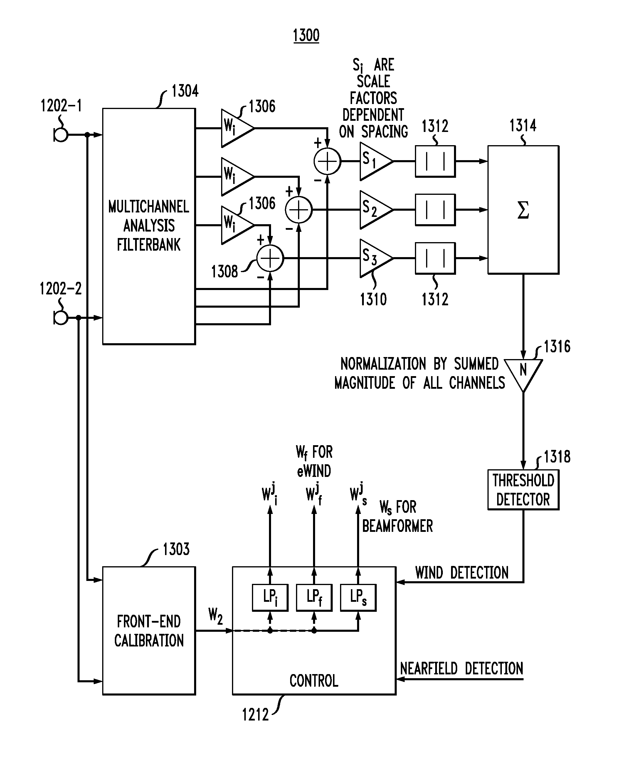
[0008]In one possible implementation, the technique combines the operation of a constrained adaptive two-element differential microphone array with a multi-microphone wind-noise suppression algorithm. The main result is the combination of these two technological solutions. First, a two-element adaptive differential microphone is formed that is allowed to adjust its directional response by automatically adjusting its beampattern to minimize wind noise. Second, the adaptive beamformer output is fed into a multichannel wind-noise suppression algorithm. The wind-noise suppression algorithm is based on exploiting the knowledge that wind-noise signals are caused by convective airflow whose speed of propagation is much less than that of desired propagating acoustic signals. It is this unique combination of both a constrained two-element adaptive differential beamformer with multichannel wind-noise suppression that offers an effective solution for mobile communication devices in varying acoustic environments.

Problems solved by technology

Wind-induced noise in the microphone signal input to mobile communication devices is now recognized as a serious problem that can significantly limit communication quality.
Wind-noise sensitivity of microphones has been a major problem for outdoor recordings.
Wind noise is also now becoming a major issue for users of directional hearing aids as well as cell phones and hands-free headsets.
A related problem is the susceptibility of microphones to the speech jet, or flow of air from the talker's mouth.

Method used


Image

  • Noise-reducing directional microphone array
  • Noise-reducing directional microphone array
  • Noise-reducing directional microphone array

Examples


Embodiment Construction

Differential Microphone Arrays

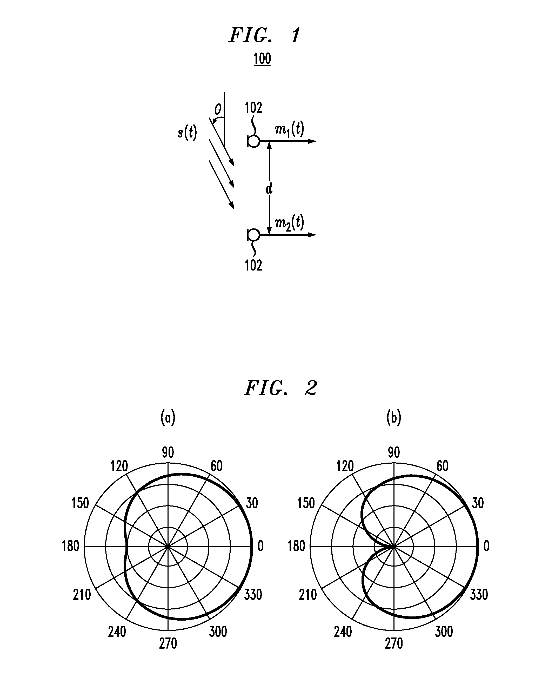
[0033]A differential microphone is a microphone that responds to spatial differentials of a scalar acoustic pressure field. The order of the differential components that the microphone responds to denotes the order of the microphone. Thus, a microphone that responds to both the acoustic pressure and the first-order difference of the pressure is denoted as a first-order differential microphone. One requisite for a microphone to respond to the spatial pressure differential is the implicit constraint that the microphone size is smaller than the acoustic wavelength. Differential microphone arrays can be seen directly analogous to finite-difference estimators of continuous spatial field derivatives along the direction of the microphone elements. Differential microphones also share strong similarities to superdirectional arrays used in electromagnetic antenna design. The well-known problems with implementation of superdirectional arrays are the same as those ...


PUM


Abstract

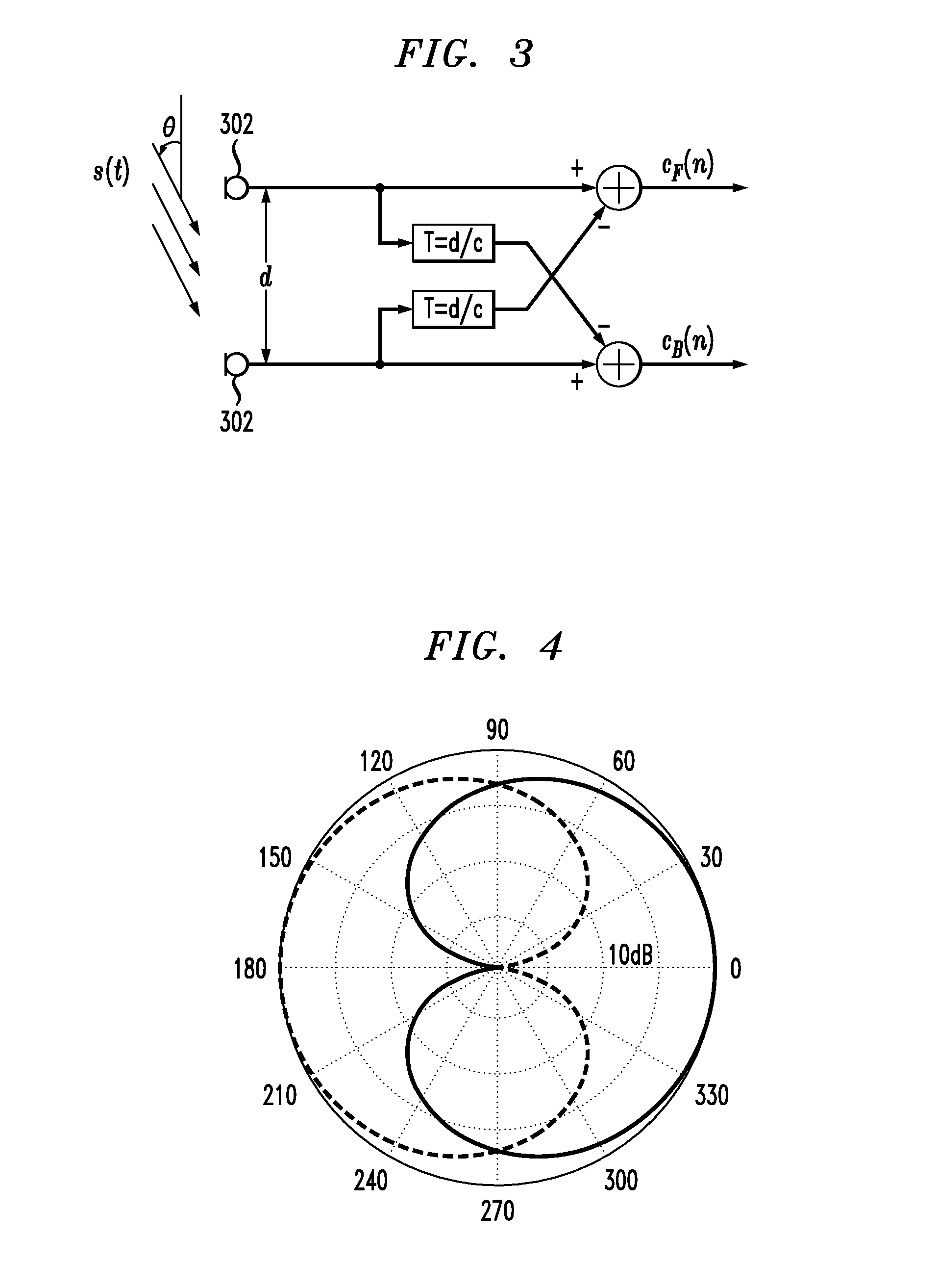
In one embodiment, a directional microphone array having (at least) two microphones generates forward and backward cardioid signals from two (e.g., omnidirectional) microphone signals. An adaptation factor is applied to the backward cardioid signal, and the resulting adjusted backward cardioid signal is subtracted from the forward cardioid signal to generate a (first-order) output audio signal corresponding to a beampattern having no nulls for negative values of the adaptation factor. After low-pass filtering, spatial noise suppression can be applied to the output audio signal. Microphone arrays having one (or more) additional microphones can be designed to generate second- (or higher-) order output audio signals.

Description

CROSS-REFERENCE TO RELATED APPLICATIONS[0001]This application is a continuation of U.S. patent application Ser. No. 12 / 281,447, filed on Sep. 2, 2008 as attorney docket no. 1053.007, the teachings of which are incorporated herein by reference. In addition, the teachings of each of PCT patent application nos. PCT / US2007 / 06093 and PCT / US2006 / 44427, U.S. Pat. No. 7,171,008, and U.S. provisional application Nos. 60 / 781,250, 60 / 737,577, and 60 / 354,650 are incorporated herein by reference.BACKGROUND OF THE INVENTION[0002]1. Field of the Invention[0003]The present invention relates to acoustics, and, in particular, to techniques for reducing wind-induced noise in microphone systems, such as those in hearing aids and mobile communication devices, such as laptop computers and cell phones.[0004]2. Description of the Related Art[0005]Wind-induced noise in the microphone signal input to mobile communication devices is now recognized as a serious problem that can significantly limit communicatio...

Claims


Application Information

Patent Timeline
Patent Type & Authority Applications(United States)
IPC IPC(8): H04B15/00
CPCG10L2021/02166H04R3/005H04R25/407H04R2430/23H04R2430/20H04R2430/21H04R2410/07H04R1/326H04R3/04G10L21/0216G10L21/0264H04R2410/01
Inventor ELKO, GARY W.MEYER, JENS M.GAENSLER, TOMAS FRITZ
Owner MH ACOUSTICS
Learn More