
Apparatus for operating interior permanent magnet synchronous motor

Active Publication Date: 2013-01-10
LSIS CO LTD
View PDF5 Cites 40 Cited by
  • Summary
  • Abstract
  • Description
  • Claims
  • Application Information

AI Technical Summary

Benefits of technology

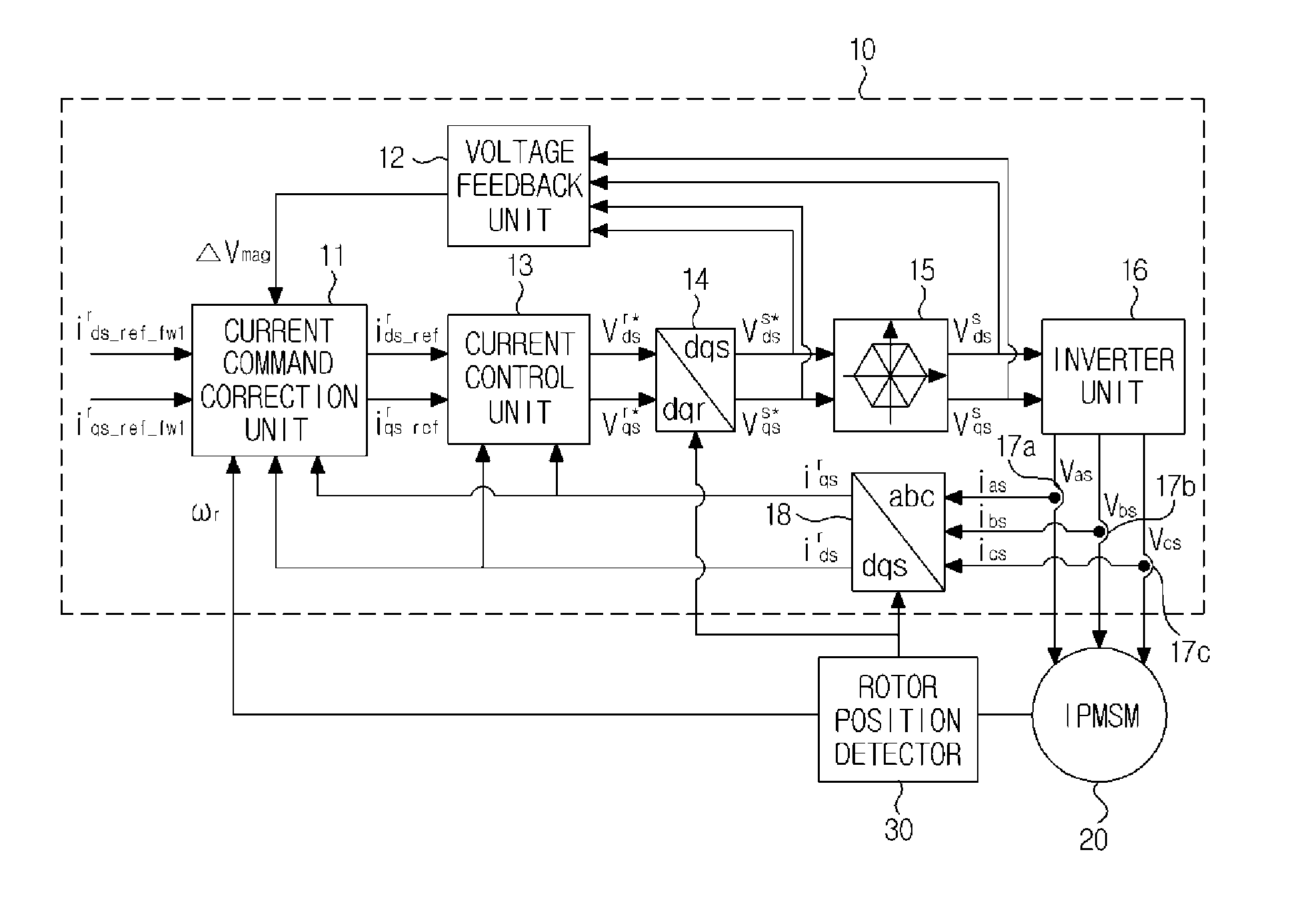
This patent aims to solve problems in the prior art by providing an apparatus for operating interior permanent magnet synchronous motors that are more robust against parameter changes, have a higher voltage utilization rate, and can follow a maximum torque even at high speeds. The apparatus reduces the difference between two voltages by minimizing the difference between the output voltage of a current control unit and the voltage actually synthesized by an inverter unit, and uses all voltage limit hexagons to increase the DC-link voltage utilization rate of the inverter unit. Additionally, the current command is corrected to hold the torque at a predetermined level, allowing the motor to achieve the maximum torque even during high-speed driving.

Problems solved by technology

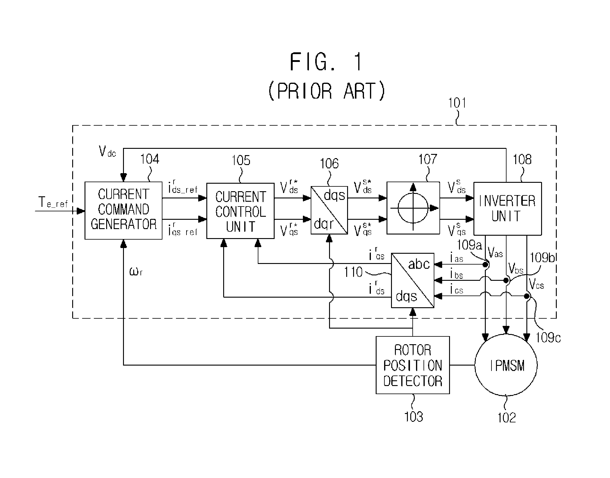
However, there is a problem in that performance of the IPMSM driving system of FIG. 1 deteriorates, because the current command generator (104) uses a pre-measured look-up table to cause subject parameters of the IPMSM to change.
Furthermore, there is another problem in that, even if the subject parameters of the IPMSM are not changed, the driving performance of motor is determined by performance of the look-up table, because the look-up table determines the performance of an entire driving region.
There is still another problem in that a voltage utilization rate of the inverter decreases to thereby decrease the output torque, because amount of voltage synthesized by the inverter is limited by the inscribed circle of the voltage limit hexagon.

Method used


Image

  • Apparatus for operating interior permanent magnet synchronous motor
  • Apparatus for operating interior permanent magnet synchronous motor
  • Apparatus for operating interior permanent magnet synchronous motor

Examples


Embodiment Construction

[0065]The disclosed embodiments and advantages thereof are best understood by referring to FIGS. 1-8 of the drawings, like numerals being used for like and corresponding parts of the various drawings. Other features and advantages of the disclosed embodiments will be or will become apparent to one of ordinary skill in the art upon examination of the following figures and detailed description. It is intended that all such additional features and advantages be included, within the scope of the disclosed embodiments, and protected by the accompanying drawings. Further, the illustrated figures are only exemplary and not intended to assert or imply any limitation with regard to the environment, architecture, or process in which different embodiments may be implemented. Accordingly, the described aspect is intended to embrace all such alterations, modifications, and variations that fall within the scope and novel idea of the present invention.

[0066]Meanwhile, the terminology used herein i...


PUM


Abstract

Provided is an apparatus for operating interior permanent magnet synchronous motor by receiving a first current command of a flux weakening control region I in a system including a detector measuring a position and a speed of a rotor of an IPMSM, the apparatus including a feedback unit transmitting over-modulated voltage information to a correction unit, the correction unit using the rotor speed and the over-modulated voltage information to correct the first current command to a second current command of a flux weakening control region II, a control unit controlling the second current command to output a voltage, a first limit unit limiting an output of the control unit to a maximum voltage synthesizable by an inverter unit, and the inverter unit applying a 3-phase voltage command for following a command torque to the IPMSM using an output of a voltage limit unit.

Description

[0001]Pursuant to 35 U.S.C.§119 (a), this application claims the benefit of earlier filing date and right of priority to Korean Patent Application No. 10-2011-0066625, filed on July 5, content of which is hereby incorporated by reference in their entirety.BACKGROUND OF THE DISCLOSURE[0002]1. Field of Endeavor The present disclosure relates to a motor driving apparatus, and more particularly to a driving apparatus for operating an interior permanent magnet synchronous motor at a speed higher than a rated speed.[0003]2. Background[0004]The information disclosed in this Background of the Invention section is only for enhancement of understanding of the background of the invention and should not be taken as an acknowledgement or any form of suggestion that this information forms the prior art that is already known to a person skilled in the art.[0005]A permanent magnet synchronous motor (PMSM) is a high-power and high-efficiency motor that is widely used as a traction motor in the field...

Claims


Application Information

Patent Timeline
IPC IPC(8): H02P21/14H02P6/06H02P6/08H02P6/28H02P21/00H02P21/22H02P27/04H02P27/08
CPCH02P21/0035H02P21/0089H02P25/021H02P21/06H02P21/22H02P25/024H02P21/14
Inventor YOO, ANNO
Owner LSIS CO LTD
Learn More