
Breakage prevention mechanism for conveying device and conveying device using breakage prevention mechanism

a technology of breakage prevention and conveying device, which is applied in the direction of metal-working feeding device, manufacturing tools, shape safety devices, etc., can solve the problems of weakest component or the most loaded component deformation or damage, heavy strain on the transferring member, etc., and achieve the effect of preventing breakage, ensuring stability of transfer work, and accurate positioning of work

Active Publication Date: 2013-01-10
AIDA ENG LTD
View PDF12 Cites 5 Cited by
  • Summary
  • Abstract
  • Description
  • Claims
  • Application Information

AI Technical Summary

Benefits of technology

The present invention is about a breakage prevention mechanism for a crossbar system transfer apparatus that can accommodate misalignment between the transferring member and the crossbar. The transfer can be performed even if there is a misalignment in the phase of the transferring member, and it prevents breakage. The mechanism includes pivotable and slidable transferring member and crossbar, which allows for the transfer of work in different directions and at different heights. A fixation retention mechanism can be used to constrain the movement of the crossbar and release it when there is an excessive external force. The mechanism can be used to transfer works in an inclined state, and it protects the crossbar from damage if there is a large displacement. The mechanism includes a sensor to detect displacement and allow for strict synchronization control of the transferring member.

Problems solved by technology

In such a cross bar system transfer apparatus, since the cross bar is moved by synchronizing a pair of transferring members, a heavy strain will be put on the transferring members, the cross bars etc., and the weakest component or the most loaded component may possibly deformed or damaged, when displacement occurs between the pair of transferring members.

Method used


Image

  • Breakage prevention mechanism for conveying device and conveying device using breakage prevention mechanism
  • Breakage prevention mechanism for conveying device and conveying device using breakage prevention mechanism
  • Breakage prevention mechanism for conveying device and conveying device using breakage prevention mechanism

Examples


Embodiment Construction

Problems to be Solved

[0010]The present invention is to provide a breakage prevention mechanism of a crossbar system transfer apparatus which prevents the deformation or breakage of a transfer member or a crossbar etc. even if the displacement of a pair of transfer members of the transfer apparatus occurs by power shutdown or a contact with a die etc. of a press machine etc. and to provide the transfer apparatus using thereof. Further, the present invention is to provide a crossbar system breakage prevention mechanism and a crossbar system transfer apparatus, which can transfer a work while being inclined right or left, or back or forth with a simple configuration, and which can make the work inclined right or left, or back or forth or can set it back on the way of transfer.

Solution

[0011]The breakage prevention mechanism of the transfer apparatus of the present invention is characterized in that it comprises a pair of transferring members that is synchronized and moves approximately ...


PUM

PropertyMeasurementUnit
Forceaaaaaaaaaa
Frictional forceaaaaaaaaaa
Displacementaaaaaaaaaa

Abstract

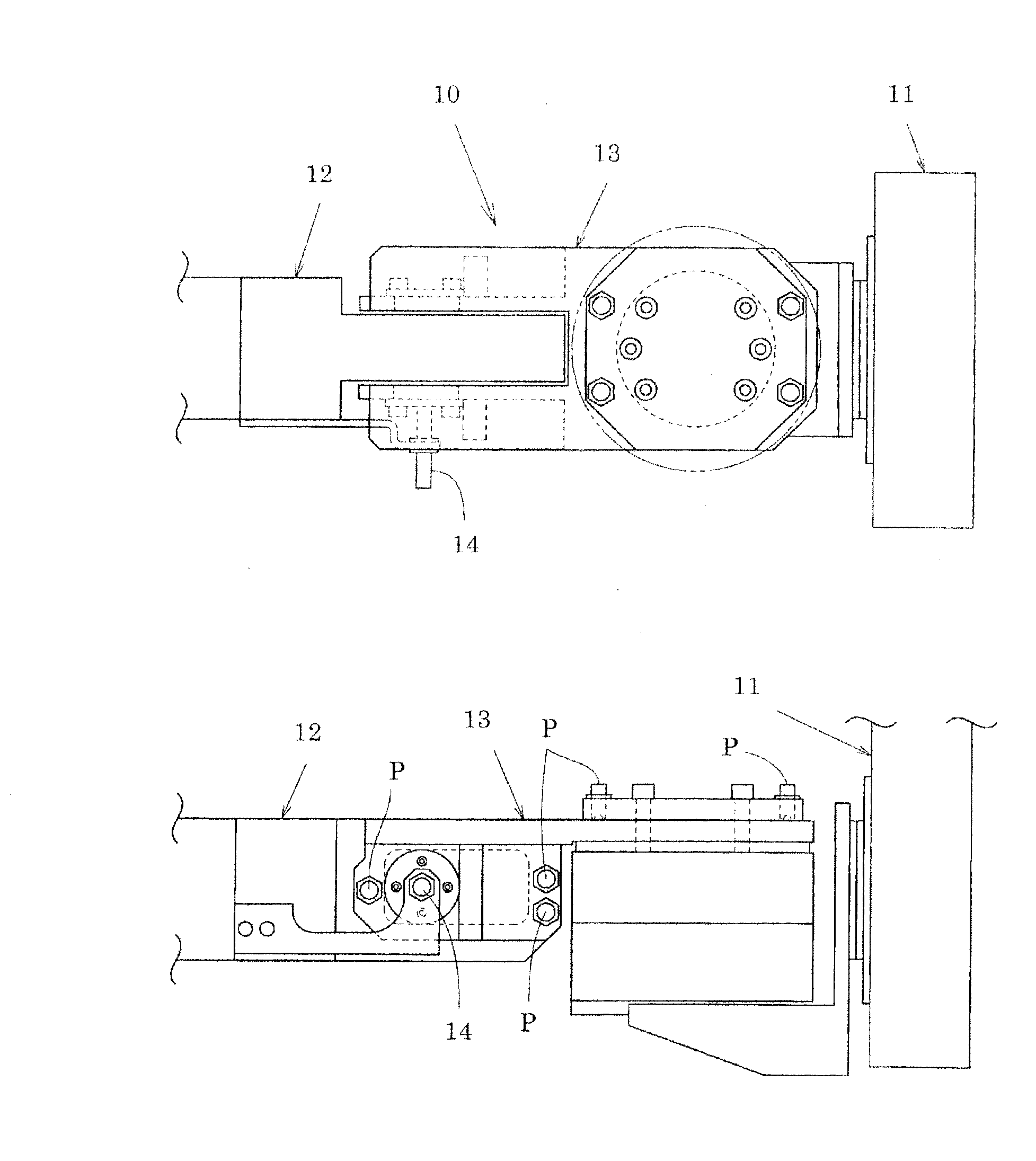
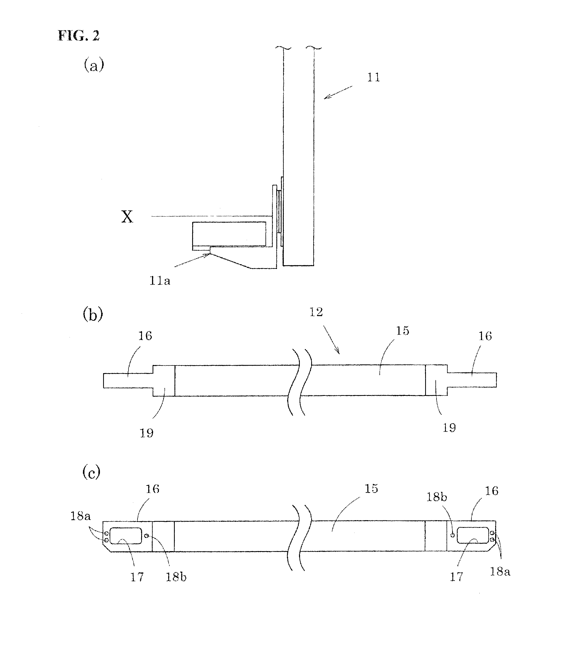
A breakage prevention mechanism includes a pair of arms which is synchronized and moves approximately parallel, and a crossbar bridged between the top end of the arms. Both end of the crossbar and the arm are connected pivotably around two axis. Both end of the crossbar are configured to be slidable against the arm in X axis direction. A plunger is placed between both end of the crossbar and arm, which protects the crossbar by restraining the pivoting and the sliding of both in the normal condition and releasing the restraint when the unintended force is given.

Description

FIELD OF THE INVENTION[0001]The present invention relates to a breakage prevention mechanism of a transfer apparatus provided in a press machine and a transfer apparatus using thereof. For further details, it relates to a breakage prevention mechanism of a crossbar system transfer apparatus and a transfer apparatus using thereof.DESCRIPTION OF BACKGROUND ART[0002]A transfer apparatus which transfers a work between a plurality of press machines or dies arranged in series is known. As transfer apparatuses like these, there are an arm system transfer apparatus which swings an arm installed in a column etc. attached between press machines and a feed bar system transfer apparatus in which a feed bar installed in a rail etc. ached between press machines is moved horizontally or vertically. Therefore, a work is held and transferred by these arms or feed bars of the transfer apparatus. Moreover, a cross bar system transfer apparatus is known, in which a pair of transferring members (arms or...

Claims


Application Information

Patent Timeline
IPC IPC(8): B65G47/00
CPCB21D43/055B21D43/052B21D43/11B21D55/00B25J11/00
Inventor TAKEDA, KEISUKENAKOSHI, SEIJIKOSHIMIZU, TAKASHI
Owner AIDA ENG LTD
Learn More