
Test Operation

a test operation and test technology, applied in the field of test operation, can solve the problems of misplaced confidence, unsustainable complexity in the management of the testing process, and insufficient functional models, and achieve the effect of simple and flexible methods

Inactive Publication Date: 2013-01-03
IBM CORP
View PDF3 Cites 3 Cited by
  • Summary
  • Abstract
  • Description
  • Claims
  • Application Information

AI Technical Summary

Benefits of technology

The invention provides a testing solution that combines functional tests with a dynamic view of the context. This allows test scenarios to exist and be validated in a changing environment. The testing method supports defining use and business requirements as eligibility criteria to be assessed and tested within that environment. The system test environment uses result buckets and scenario eligibility criteria to validate test scenarios against use case requirements, rather than individual functional components. This simplifies test scenario management for multiple test requirements. The validated events are used to populate result buckets, which can be any task or scenario being assessed. The separation of eligibility criteria and result buckets from actual test processing or validation allows for a massive simplification of the scenario, the ability to reuse it in different environments, and reduces risk to the test team.

Problems solved by technology

However, this approach can often result in a misplaced confidence that functional coverage can be equated to product quality, or usage.
In complex systems with multiple users concurrently exercising different product functionality, often using common resources, the functional model is often inadequate or, at best, rapidly reaches a point where it has an unsustainable level of complexity in order to manage the testing process.
Issues of scale, longevity, workload and fluctuations in work patterns all combine to create a grey area where individual elements of a test may succeed but, when combined, will fail to achieve the ultimate goal of the test scenario.
The ability to relate this to the fluctuations or reasonable changes or failures would either be a post-processing task or would require extremely complex modelling.
The complexity of modelled scenarios is largely because, for functional tests, the environment and scenario are created to enable the test case that is being checked to be validated as a pass or fail.

Method used


Image

  • Test Operation
  • Test Operation
  • Test Operation

Examples


Embodiment Construction

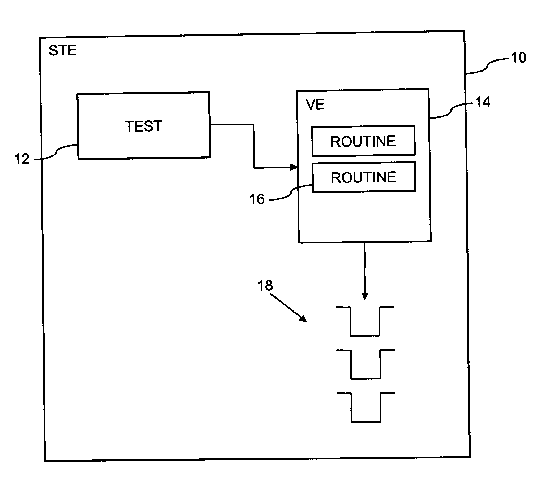
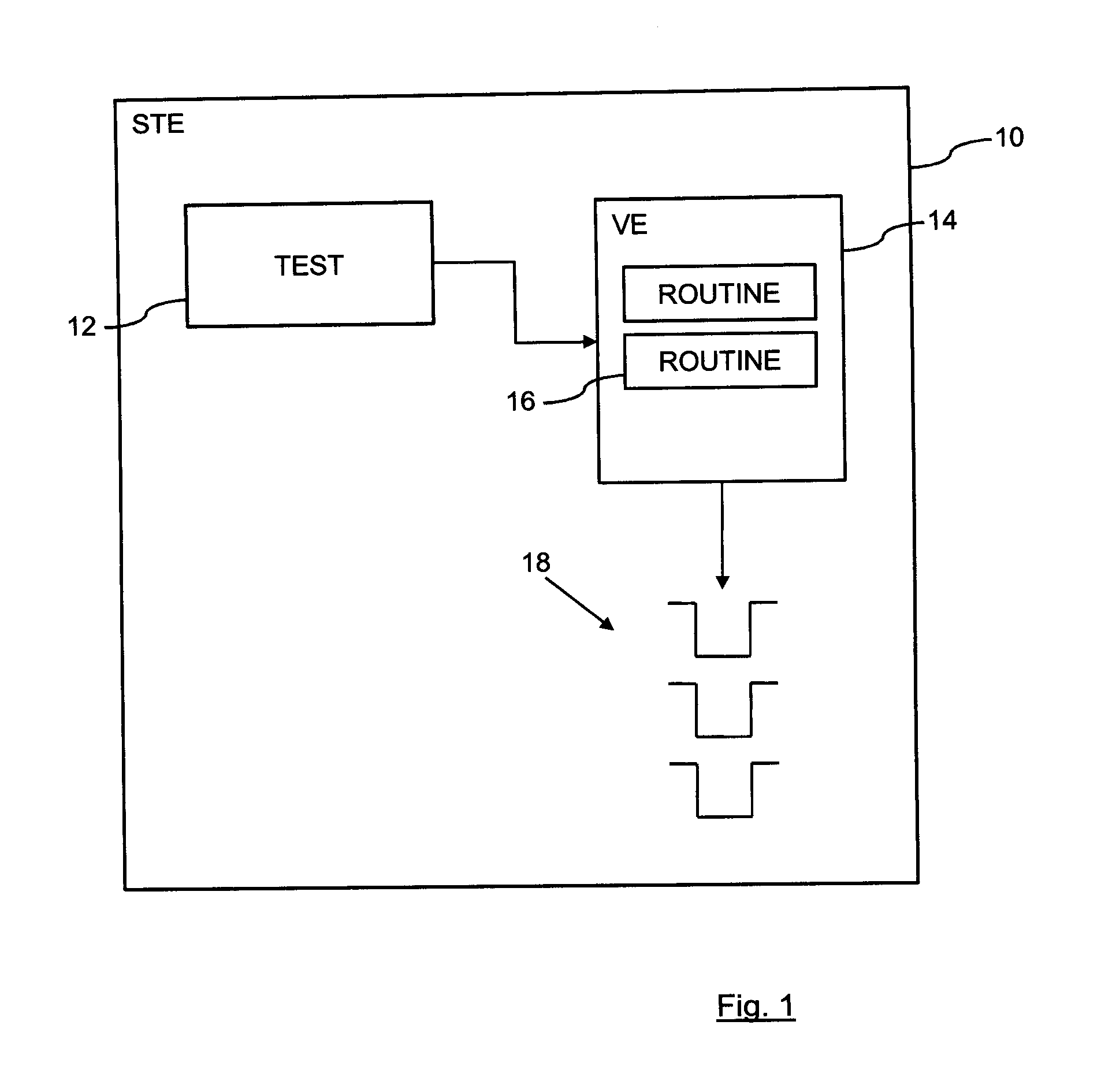
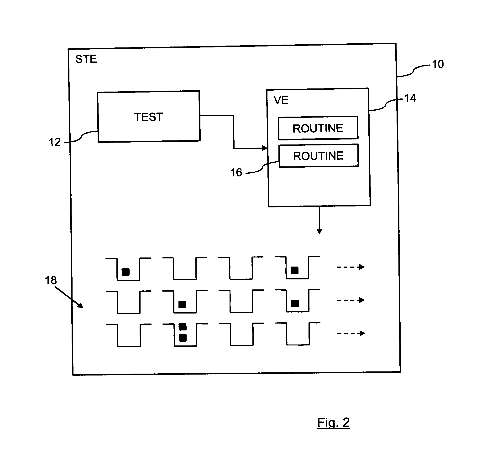
[0021]FIG. 1 shows an example of a system test environment 10. In the system test environment 10 a processing function runs one or more tests 12 on systems that need to be tested. When the tests 12 are run, they generate events which are then passed to a validation environment 14 for evaluation by validation routines 16. An event might be a link to an object or a communication between two specific components within the system being tested. The validation routines 16 are designed to listen for the events that are relevant to the respective routines 16. As the validation routines 16 process the events that they receive, they populate result buckets 18.

[0022]The population of the buckets 18 can be based on a standard format for the content and a naming convention that allows the purpose of the bucket 18, for example a count of how many transactions are routed over different connection types, to be identified by any test scenario that wishes to use the information in the individual buck...


PUM


Abstract

A method of operating a test in a test environment comprises running the test, detecting the generation of events during the test and for each detected event, populating one or more result buckets according to one or more validation routines. Each validation routine defines a result to add to a result bucket according to a characteristic of the detected event. Once the test is completed, or during the running of the test, one or more test scenarios are run against the result buckets, with each test scenario returning an outcome according to one or more algorithms processing the results in the result buckets. In a preferred embodiment, the populating of the one or more result buckets is according to validation routines that populate a matrix of result buckets, each result bucket being populated during a specific time period.

Description

BACKGROUND[0001]This invention relates to a method of, and system for, operating a test in a test environment. In one embodiment, the invention provides a method for better identifying confidence in a test scenario to distinguish the grey area between a pass and a fail.[0002]Test plans, test cases and, in particular, automated tests are based upon a very distinct divide between pass and fail. These tests presume that given a specific set of circumstances and actions a specific result will always be returned. If it does the test is passed, but if not the test is failed. For simple functional tests this is often perfectly adequate. Even for large complicated environments, where the number of functions and the complexity of their interactions have increased the number of tests exponentially, it is still possible to validate individual results in this way. Indeed, methodologies such as model-based testing rely on the ability to map every individual path through code to validate that eac...

Claims


Application Information

Patent Timeline
Patent Type & Authority Applications(United States)
IPC IPC(8): G06F19/00
CPCG06F11/3692G06F11/3688
Inventor BAYLIS, MICHAELKEY, DAVID M.YATES, WILLIAM L.
Owner IBM CORP
Learn More