Nonaqueous electrolyte secondary battery
- Summary
- Abstract
- Description
- Claims
- Application Information
AI Technical Summary
Benefits of technology
Problems solved by technology
Method used
Image
Examples
example 1
Fabrication of Positive Electrode Plate
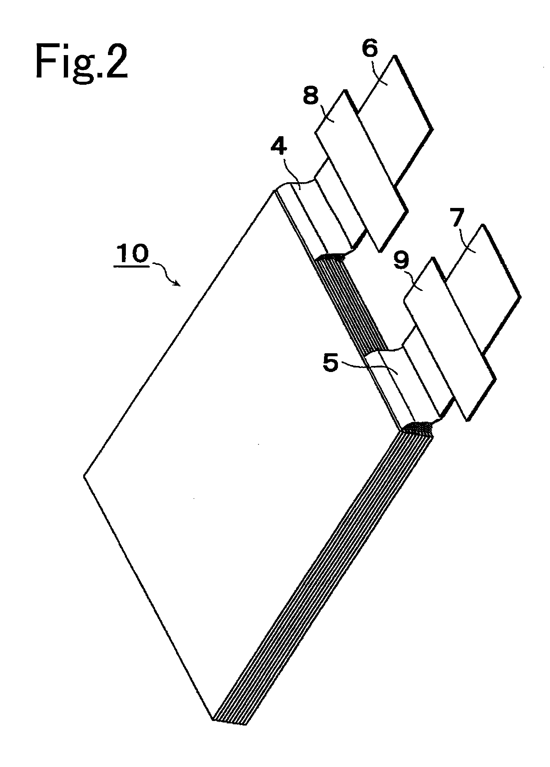
[0052]A positive electrode slurry was prepared by mixing 94 parts by weight of Li(Ni1 / 3Col1 / 3Mn1 / 3)O2 to serve as the positive electrode active material, three parts by weight of carbon black to serve as conducting agent, and three parts by weight of polyvinylidene fluoride to serve as binding agent, in a solution of N-methyl-2-pyrrolidone (NMP) serving as solvent. Next, this positive electrode slurry was spread over one side or both sides of aluminum foils (thickness 20 μm) serving as the positive electrode substrate 2a. Then the solvent was allowed to dry and the resulting items were pressed by a roller, after which, as shown in FIG. 3, they were cut to width (L1)=145 mm and length (L2)=150 mm, and moreover so that a portion of aluminum foil where no positive electrode active material layer 2b was formed (width L3=30 mm, length L4=20 mm) protruded from one edge of the positive electrode plate 2 as the positive electrode collector tab 4, to co...
example 2
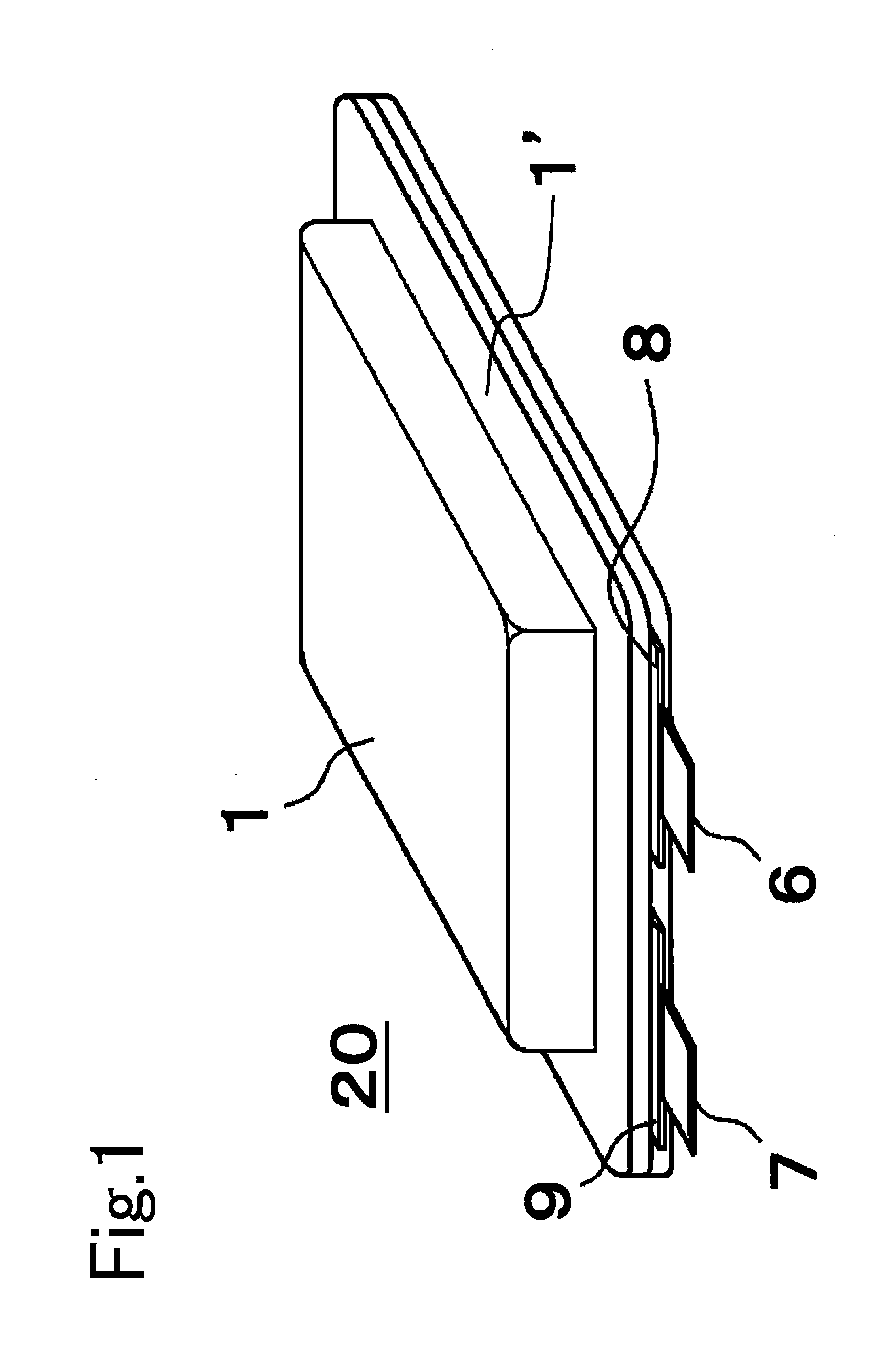
[0063]Except for the structure of the stacked electrode assembly 10, the prismatic lithium ion secondary battery 20 of Example 2 was fabricated using the same methods as for that of Example 1. The stacked electrode assembly 10 for Example 2 was fabricated by the following method.
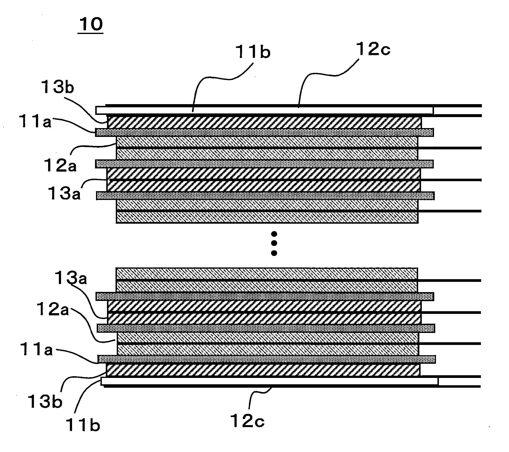
[0064]Twenty four both-sides-coated positive electrode plates 12a and twenty three both-sides-coated negative electrode plates 13a were stacked alternately, with separators 11a interposed that were microporous films of polyethylene, on one side of which a layer constituted of alumina particles and polyvinyl alcohol was formed. Then, as FIG. 5 shows, a single-side-coated negative electrode plate 13b was disposed, with a separator 11a interposed, on each both-sides-coated positive electrode plate 12a located at the two outermost edges of the stacked electrode assembly, in such a manner that the negative electrode active material layer 3b was positioned toward the center, in the stacking direction, of the stack...
example 3
[0065]Except for the structure of the stacked electrode assembly 10, the prismatic lithium ion secondary battery 20 of Example 3 was fabricated using the same methods as for that of Example 1. The stacked electrode assembly 10 for Example 3 was fabricated by the following method.
[0066]Twenty three both-sides-coated positive electrode plates 12a and twenty four both-sides-coated negative electrode plates 13a were stacked alternately, with separators 11a interposed that were microporous films of polyethylene, on one side of which a layer constituted of alumina particles and polyvinyl alcohol was formed. Then, as FIG. 6 shows, a single-side-coated positive electrode plate 12b was disposed, with a separator 11a interposed, on each both-sides-coated negative electrode plate 13a located at the two outermost edges of the stacked electrode assembly, in such a manner that the positive electrode active material layer 2b was positioned toward the center, in the stacking direction, of the stack...
PUM
 Abstract
Description
Claims
Application Information
 - R&D
- Intellectual Property
- Life Sciences
- Materials
- Tech Scout
- Unparalleled Data Quality
- Higher Quality Content
- 60% Fewer Hallucinations
Browse by: Latest US Patents, China's latest patents, Technical Efficacy Thesaurus, Application Domain, Technology Topic, Popular Technical Reports.
© 2025 PatSnap. All rights reserved.Legal|Privacy policy|Modern Slavery Act Transparency Statement|Sitemap|About US| Contact US: help@patsnap.com


