Wireless measuring apparatus and wireless temperature measurement system

a technology of temperature measurement system and measuring apparatus, which is applied in the direction of vibration measurement in solids, heat measurement, instruments, etc., can solve the problems of insufficient intensity of measuring damped oscillatory waves and transmitting electromagnetic waves from temperature, and achieve the effect of stable frequency measuremen

Inactive Publication Date: 2013-01-03
FURUYA KINZOKU KK
View PDF5 Cites 14 Cited by
  • Summary
  • Abstract
  • Description
  • Claims
  • Application Information

AI Technical Summary

Benefits of technology

[0018]According to the present invention, it is possible that the frequency of high frequency electricity supplied to the circuitry is changed and a frequency (the resonance frequency of a sensor unit) when high frequency electricity

Problems solved by technology

However, in Non-Patent document 1 or in Patent documents 1 and 2, a problem arose in that in the case where damped oscillatory waves from the temperature sensor (or the tag) are received to obtain information such as temperature from the frequency of the damped oscillatory waves, the intensities of transmitt

Method used


Image

  • Wireless measuring apparatus and wireless temperature measurement system
  • Wireless measuring apparatus and wireless temperature measurement system
  • Wireless measuring apparatus and wireless temperature measurement system

Examples


first embodiment

1. First Embodiment

[0025](1) Configuration of Wireless Measuring Apparatus

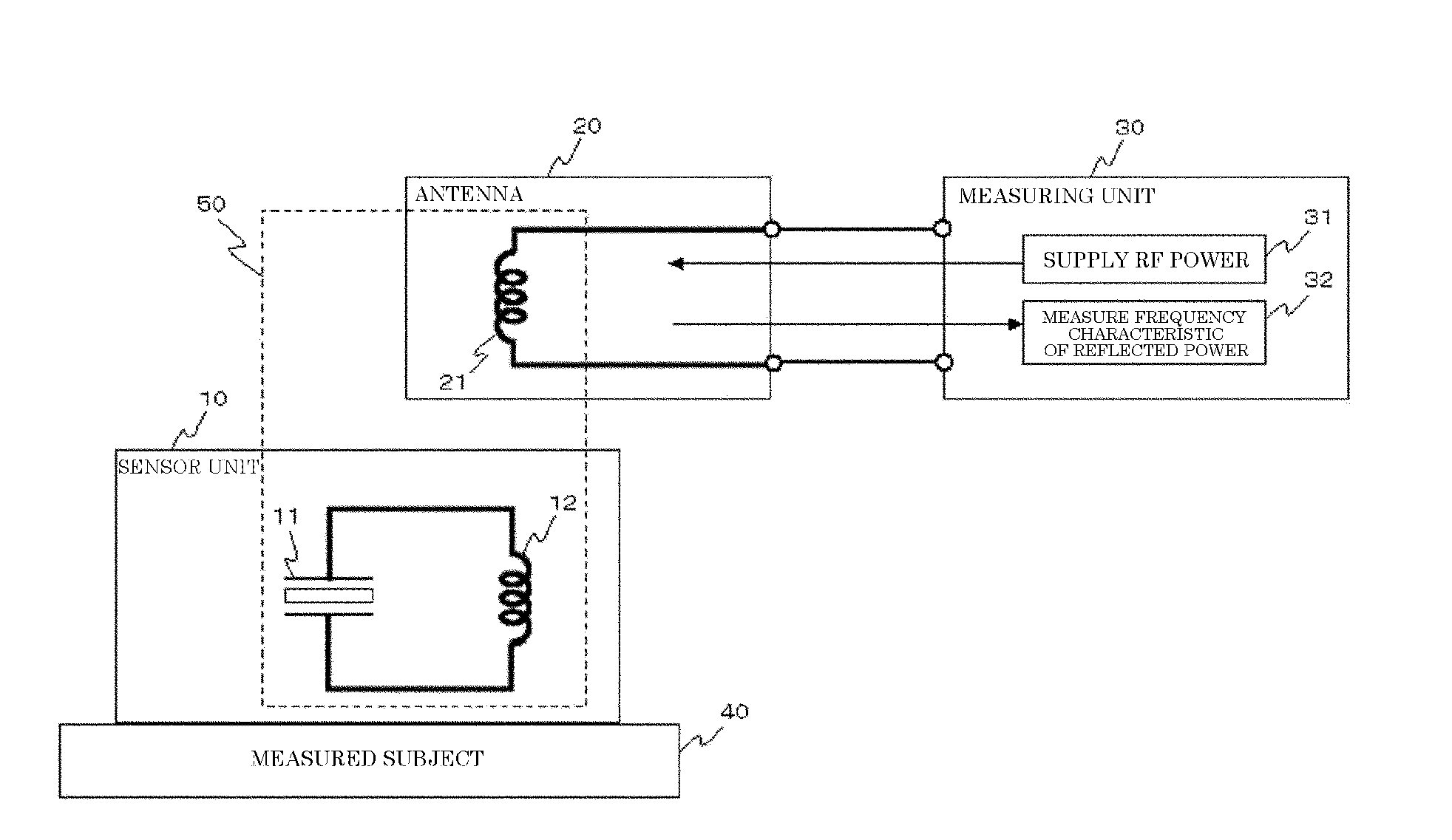
[0026]FIG. 1 is a pattern diagram illustrating an exemplary overall structure of a wireless measuring apparatus according to a first embodiment of the present invention. As illustrated in FIG. 1, the wireless measuring apparatus is a wireless measuring apparatus that measures the frequency characteristics of a sensor unit 10 mounted on an object 40 to be measured, in a configuration to include the sensor unit 10 having a piezo-resonator 11, an antenna 20 that forms a circuitry with the sensor unit 10, and a measuring means 30 that supplies high frequency electricity changed in different frequency to the circuitry and measures the frequency characteristics of the reflected electricity strength received from the circuitry.

[0027]Moreover, the wireless measuring apparatus equivalently forms a serial resonant circuit 50 using the sensor unit 10 and the antenna 20.

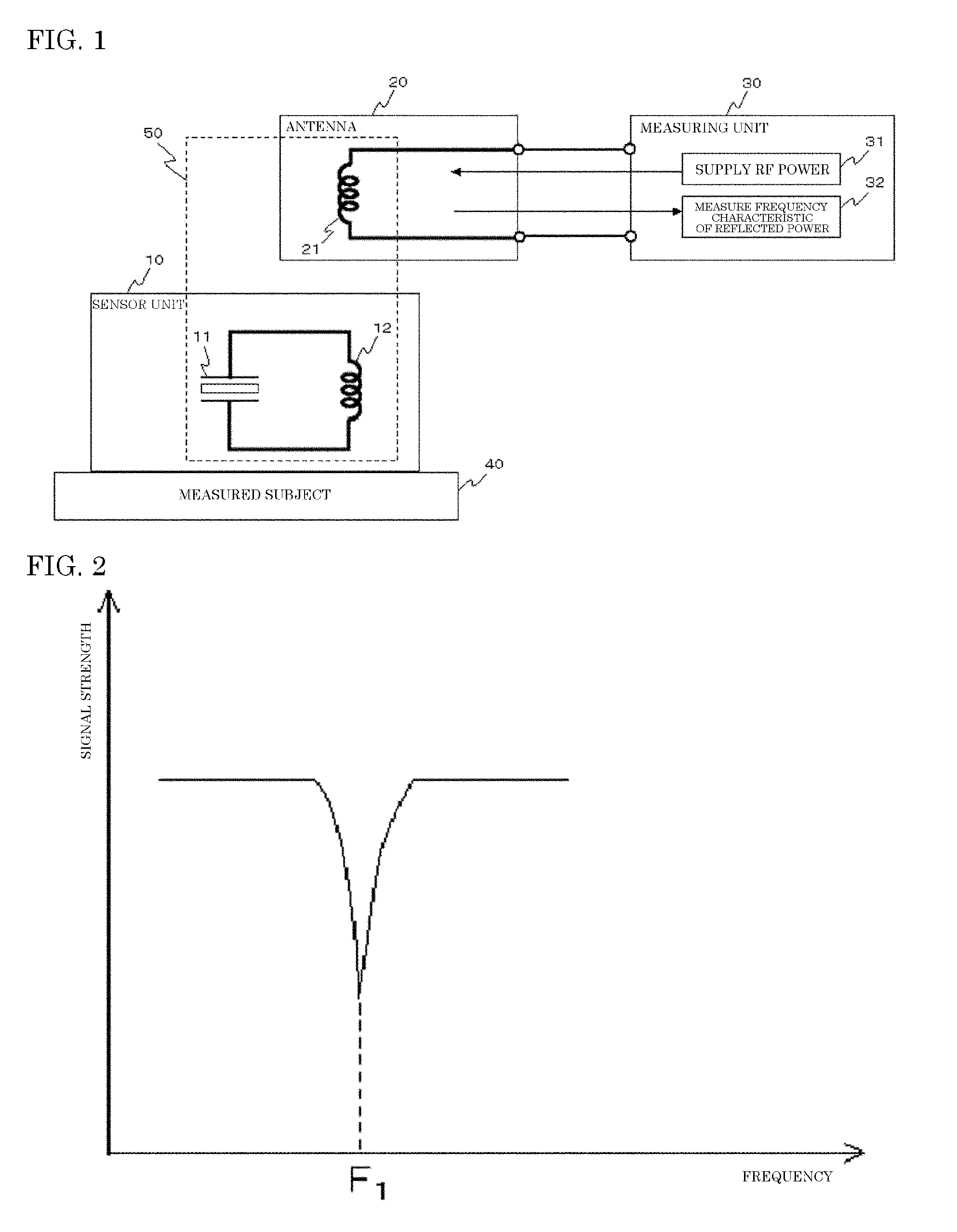
[0028]The measuring means 30 supplies high frequency...

second embodiment

2. Second Embodiment

[0042](1) Configuration of Wireless Measurement System

[0043]Next, a wireless measurement system using the wireless measuring apparatus explained above will be described. FIG. 3 is a pattern diagram illustrating an exemplary overall structure of a wireless measurement system according to a second embodiment of the present invention. As illustrated in FIG. 3, the wireless measurement system has temperature sensors, a loop antenna, a temperature measuring apparatus, and a measuring computer.

[0044]The temperature sensor has a piezo-resonator that the oscillation frequency is changed depending on temperature and a coil connected to the piezo-resonator in parallel, and a plurality of temperature sensors are disposed near the loop antenna.

[0045]The temperature sensors and the loop antenna form a circuitry, and a serial resonant circuit is equivalently formed at a certain frequency.

[0046]The temperature measuring apparatus supplies high frequency electricity changed in d...


PUM


Abstract

There is provided a wireless measuring apparatus that efficiently measures the frequency characteristics of a sensor unit mounted on an object to be measured. The wireless measuring apparatus is a wireless measuring apparatus that measures the frequency characteristics of a sensor unit (10) mounted on an object (40) to be measured, including the sensor unit (10) having a piezo-resonator (11), an antenna (20) that forms a circuitry with the sensor unit (10), and a measuring element (30) that supplies high frequency electricity changed in different frequency to the circuitry and measures the frequency characteristics of the reflected electricity strength received from the circuitry.

Description

TECHNICAL FIELD[0001]The present invention relates to a wireless measuring apparatus using an electrically resonant element such as a piezoelectric vibrator.BACKGROUND ART[0002]Conventionally, there is a wireless temperature measuring apparatus using a quartz crystal unit that the resonance frequency of the quartz crystal unit is greatly changed with respect to temperature for a piezo-resonator, in which an element having a coil connected to the quartz crystal unit in parallel is used for a temperature sensor unit. In this apparatus, the temperature sensor unit receives electromagnetic waves intermittently emitted from the transmission side. In the case where the frequency of the electromagnetic waves is matched with the oscillation frequency of the temperature sensor unit, the frequency becomes a resonance frequency, and the temperature sensor unit emits electromagnetic waves at the resonance frequency as damped oscillatory waves. The wireless temperature measuring apparatus receiv...

Claims


Application Information

Patent Timeline
IPC IPC(8): G01K11/22G01H13/00
CPCG01K7/32G01K1/024G01K1/02G01R29/22
Inventor FUKUDA, TSUGUOSATO, MITSURUKOJIMA, JUNICHIKOIKE, YUKINAGA
Owner FURUYA KINZOKU KK
Why Eureka
Try Eureka