
Imaging apparatus, imaging apparatus control method, and computer program

a control method and imaging technology, applied in the field of imaging apparatus control method, can solve the problems of poor photo quality, time-consuming and laborious to determine the focus position, and poor photo quality, and achieve the effect of more certain focus processing and effective focus processing

Active Publication Date: 2013-01-03
SONY CORP
View PDF5 Cites 0 Cited by
  • Summary
  • Abstract
  • Description
  • Claims
  • Application Information

AI Technical Summary

Benefits of technology

This patent is about a camera system that uses face detection and monitoring information to quickly and accurately focus on subjects. The system selects and applies information from various camera modes to achieve optimal focus control. It also controls the power consumption of the autofocus illuminator based on the distance to the subject. The system performs two scanning processes: one using information from face detection and monitoring, and another using a wider range of movement. The second scan is executed only if the focus position is not detected in the first scan. This ensures more certain focus control, especially in situations where a target is not easily detected. Overall, the patent offers a faster, more precise, and efficient method for autofocus and focus control in cameras.

Problems solved by technology

With shooting employing auto-focus (AF), lens driving is generally performed with a range between the near side and the infinity side as a scan range, which results in a problem that it takes time to determine a focus position.
Also, while Japanese Unexamined Patent Application Publication No. 2003-241069 and Japanese Unexamined Patent Application Publication No. 2005-260792 disclose arrangements wherein a warning is displayed regarding whether the mode will be a normal photography mode or macro photography mode based on measured distance information, issuing such a warning can often lead to missing a photo opportunity.
Accordingly, there is no focus limit for each region as with the above-mentioned Japanese Unexamined Patent Application Publication No. 2003-241069 and Japanese Unexamined Patent Application Publication No. 2005-260792, so poor photos are seldom obtained.
However, such icon display processing is primarily based on focus information from during monitoring AF, and may result in trouble such as, in the event of the user changing the angle by panning, tilting, zooming, or the like, just before the time of shooting, the monitoring AF requires time to catch up, resulting in inappropriate icons, or no icon being displayed even though the focus position is in the macro region or magnifying glass region.
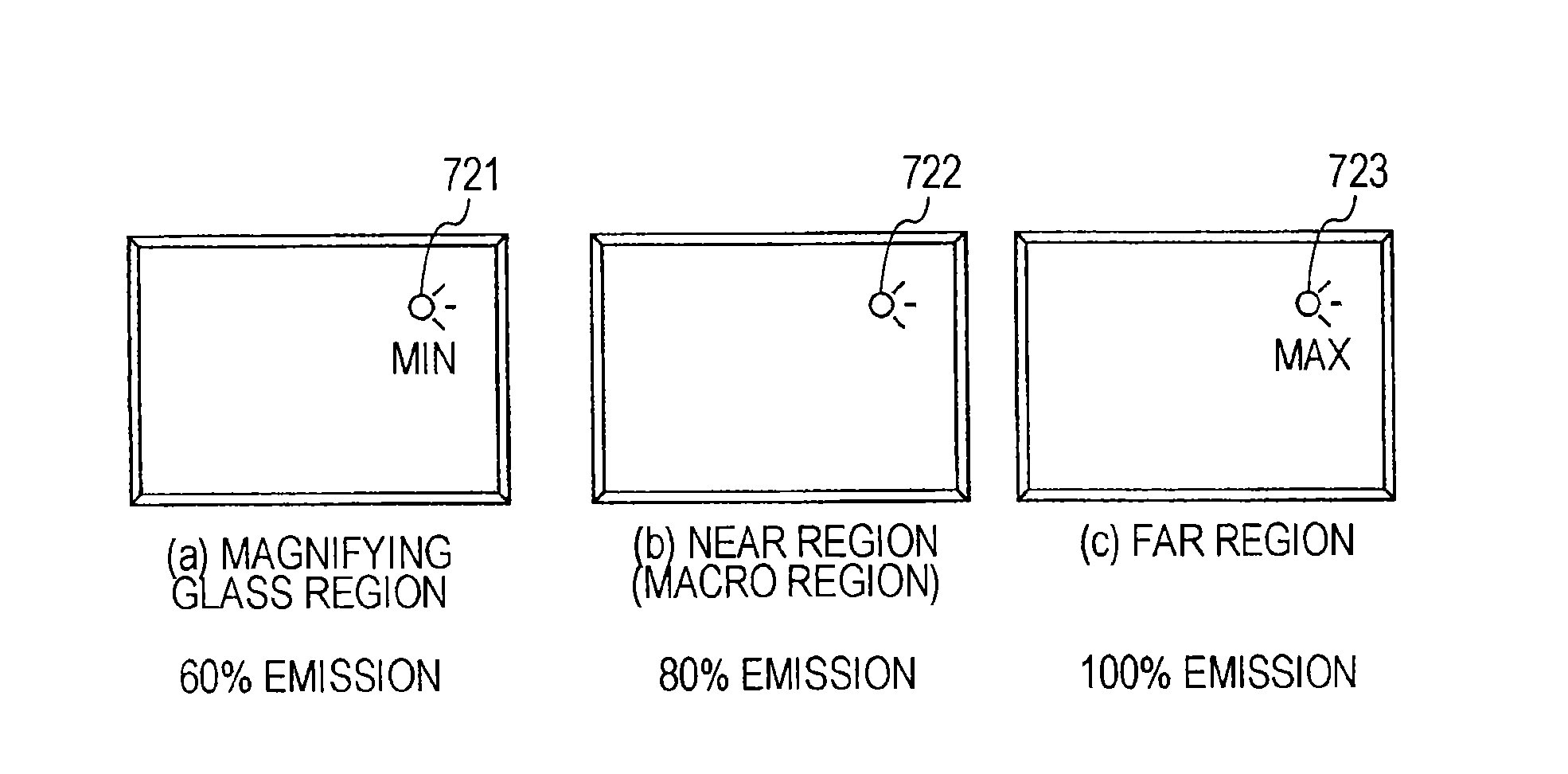
However, many of such cameras are configured to perform photography emitting light of the same intensity regardless of whether the subject is in the macro region or magnifying glass region, or the normal far region, meaning that the light is often excessive when in the macro region or magnifying glass region, and further electric power is excessively consumed.

Method used


Image

  • Imaging apparatus, imaging apparatus control method, and computer program
  • Imaging apparatus, imaging apparatus control method, and computer program
  • Imaging apparatus, imaging apparatus control method, and computer program

Examples


Embodiment Construction

[0083]Description will be made regarding the details of an imaging apparatus, imaging apparatus control method, and computer program, according to an embodiment of the present invention, with reference to the drawings.

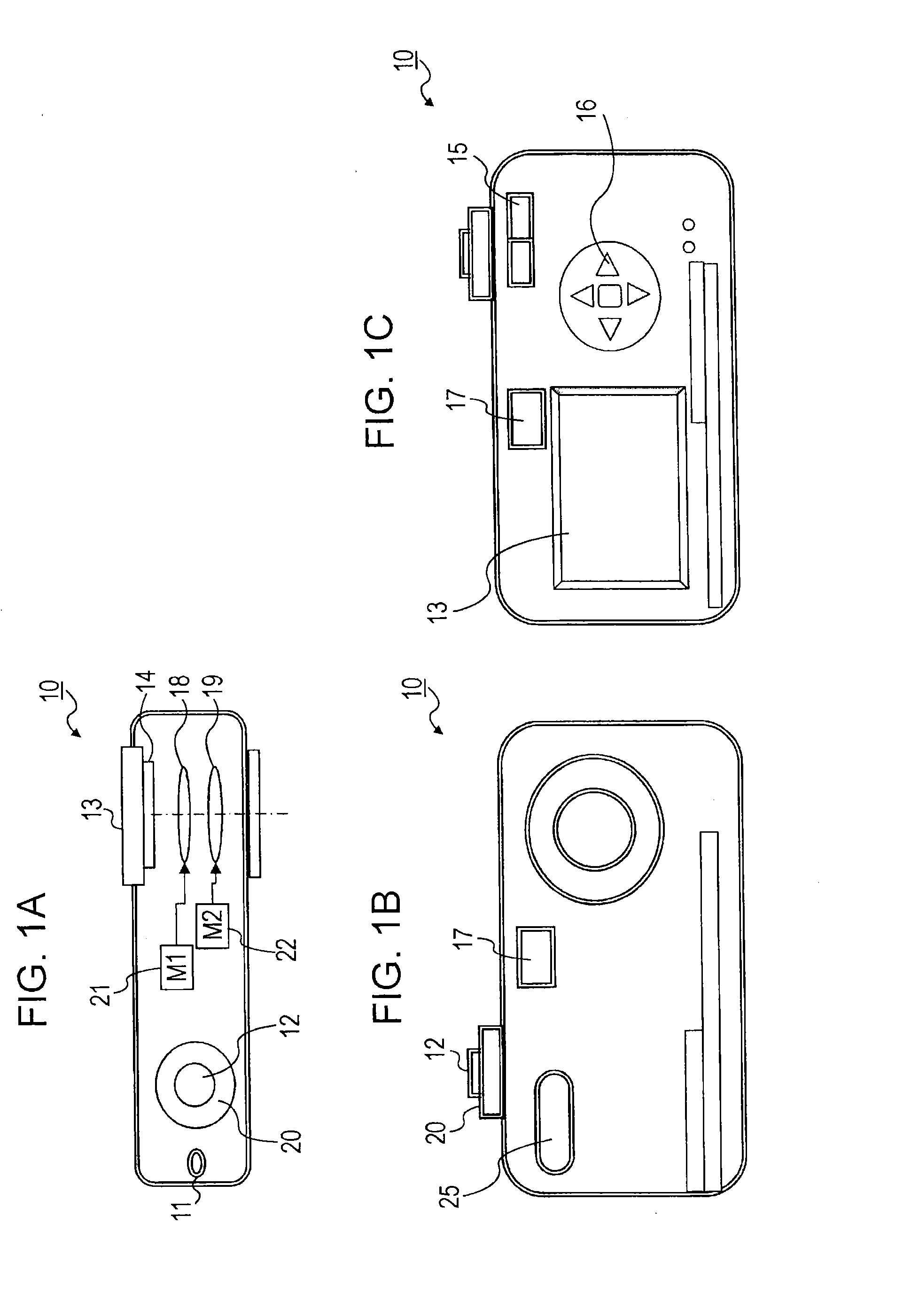
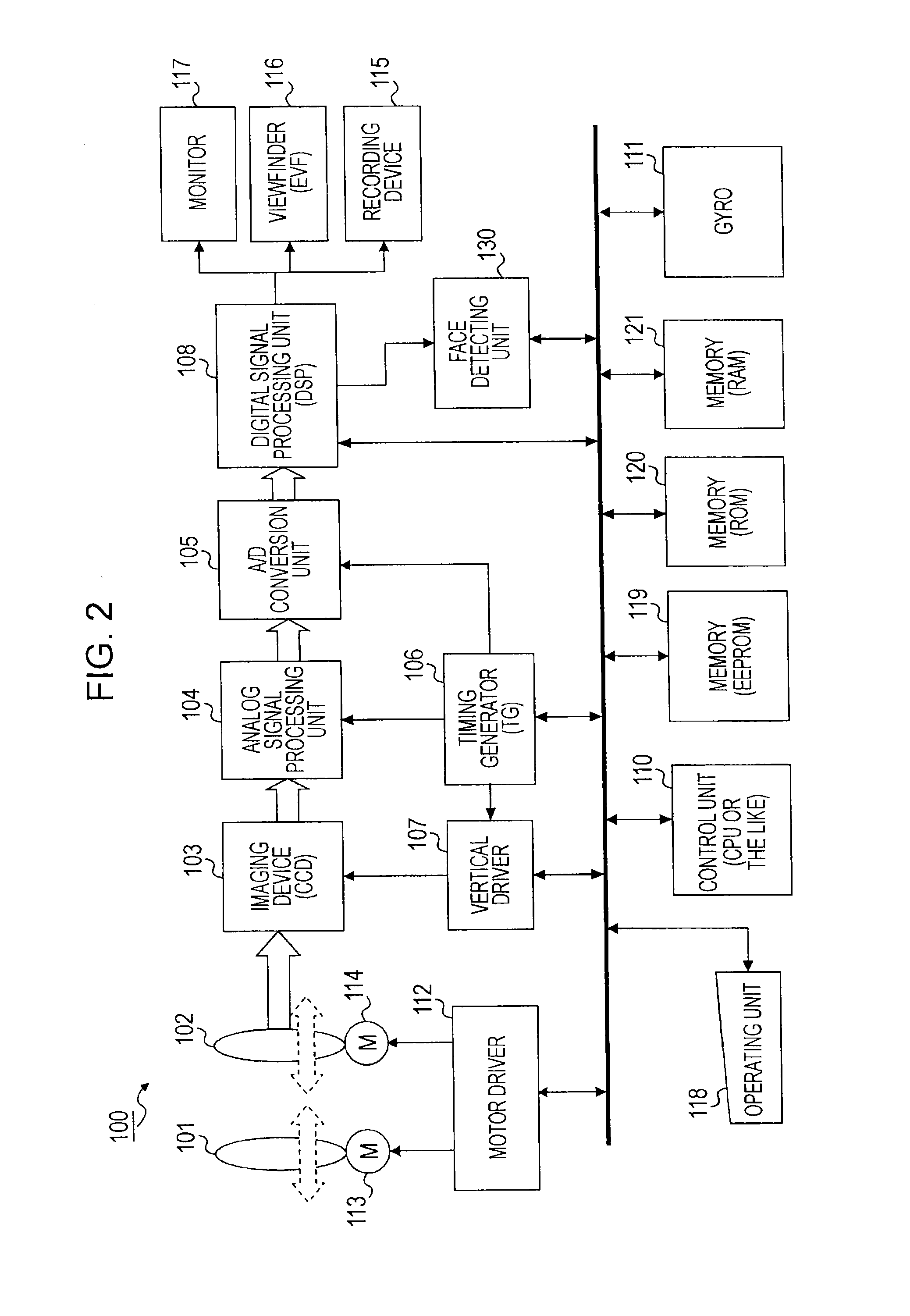
[0084]First, description will be made regarding a configuration example of an imaging apparatus according to an embodiment of the present invention, with reference to FIGS. 1A through 2. FIGS. 1A through 1C are diagrams illustrating the external view of an imaging apparatus 10 according to an embodiment of the present invention. FIG. 1A shows a top view of the imaging apparatus 10, FIG. 1B shows a front view, and FIG. 1C shows a rear view. A lens portion of the top view in FIG. 1A is illustrated as a cross-sectional view. The imaging apparatus 10 includes a power supply switch 11, release switch 12 serving as a trigger for setting image capturing timing, i.e., a shutter, monitor 13 for displaying an image (through image) shot by the image apparatus, operating informati...


PUM


Abstract

An imaging apparatus includes: a control unit configured to move a focusing lens, and detect a focus position; wherein the control unit executes auto-focus (AF) scan processing in which only a part of a range of movement of the focusing lens is set as a scan range, as first scan processing, and executes auto-focus (AF) scan processing in which a region including a region differing from the scan region of the first scan processing is set as a scan range, as second scan processing, in the event that a focus point is not detected in the first scan processing.

Description

CROSS REFERENCES TO RELATED APPLICATIONS[0001]This application is a continuation of U.S. application Ser. No. 12 / 358,917, filed Jan. 23, 2009, and is based upon and claims the benefit of priority from Japanese Application JP 2008-014455 filed Jan. 25, 2008, and Japanese Application JP 2008-190505 filed Jul. 24, 2008, the entire contents of each of which are incorporated herein by reference.BACKGROUND OF THE INVENTION[0002]1. Field of the Invention[0003]The present invention relates to an imaging apparatus, imaging apparatus control method, and computer program. More particularly, the present invention relates to an imaging apparatus, imaging apparatus control method, and computer program, which perform focus control.[0004]2. Description of the Related Art[0005]With a great number of current imaging apparatuses nowadays such as still cameras, video cameras, and so forth, an auto-focus (AF) mechanism is implemented, which automatically focuses on a subject. For example, with focus con...

Claims


Application Information

Patent Timeline
Patent Type & Authority Applications(United States)
IPC IPC(8): G09G5/00
CPCG03B13/00
Inventor MISE, TETSUONEMOTO, HIROYUKISHINTAKU, EIJIYAMAUCHI, MANABUONO, TOSHIKI
Owner SONY CORP
Learn More