
Compact antenna system having folded dipole and/or monopole

a compact antenna and dipole technology, applied in the field of compact antenna systems, can solve the problems of not being able to provide adequate antennas and associated ground planes in the device, being difficult to provide for adequate antennas and associated ground planes embedded in the device, and being too large for adequate ground planes to fit in the device below a certain siz

Active Publication Date: 2013-01-03
NETGEAR INC
View PDF7 Cites 19 Cited by
  • Summary
  • Abstract
  • Description
  • Claims
  • Application Information

AI Technical Summary

Benefits of technology

The present invention relates to a compact antenna system comprising a folded dipole and / or a monopole. The antenna system can be used in a single mode or can operate in both monopole and dipole modes. The antenna system can be mounted on a curved surface and can be printed on a flexible substrate and used as a printed circuit. The technical effects of the invention include a smaller size, wider bandwidth, and improved efficiency of the antenna system. Additionally, the invention allows for the creation of a multi-antenna system with a shared ground plane and offers opportunities for polarization and mode switching.

Problems solved by technology

However, as the size of portable devices decreases below a quarter of a wavelength of an antenna operating frequency, it becomes challenging to provide for adequate antennas and associated ground planes embedded in the device.
For example, a quarter-wavelength monopole antenna may not fit in devices below a certain size, depending on operating frequency.
Adequately sized ground planes may also be too large to fit in devices below a certain size.
In addition, it is difficult to provide multiple antennas with adequate isolation and / or envelope correlation coefficient in such physically small devices, for example for facilitating antenna diversity or multi-input multi-output (MIMO) communications.
However, such antennas come with limitations, and it remains difficult to provide an antenna or multi-antenna system which exhibits acceptable performance for a given application, for example as measured by factors such as gain, efficiency, bandwidth, q-factor, antenna isolation, and envelope correlation coefficient.

Method used


Image

  • Compact antenna system having folded dipole and/or monopole
  • Compact antenna system having folded dipole and/or monopole
  • Compact antenna system having folded dipole and/or monopole

Examples


Embodiment Construction

Definitions

[0023]The term “antenna” refers to a system of conductive elements, which radiate an electromagnetic field in response to an appropriate alternating voltage and / or current applied to one or more elements of the system, or which produce an alternating voltage and / or current when placed in an appropriate electromagnetic field, or both. An antenna may comprise active elements only, or both active and passive elements. Active elements are conductive elements which are directly coupled to an electrical source and / or sink such as a radiofrequency (RF) front-end, antenna feedpoint, or the like, typically via a transmission line. Passive elements, such as parasitic elements, reflectors, directors, counterpoises, ground plane portions, and the like, may not be directly coupled to an electrical source and / or sink, but these elements nevertheless interact electromagnetically, or electrically (for example capacitively or inductively) with other elements to contribute to functionality...


PUM

PropertyMeasurementUnit
Angleaaaaaaaaaa
Massaaaaaaaaaa
Flexibilityaaaaaaaaaa

Abstract

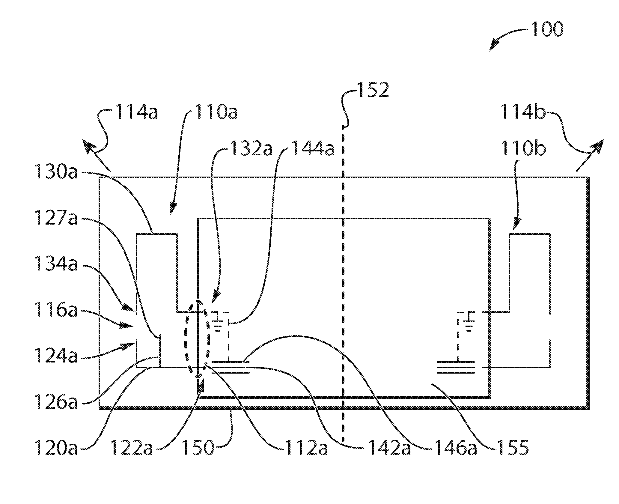
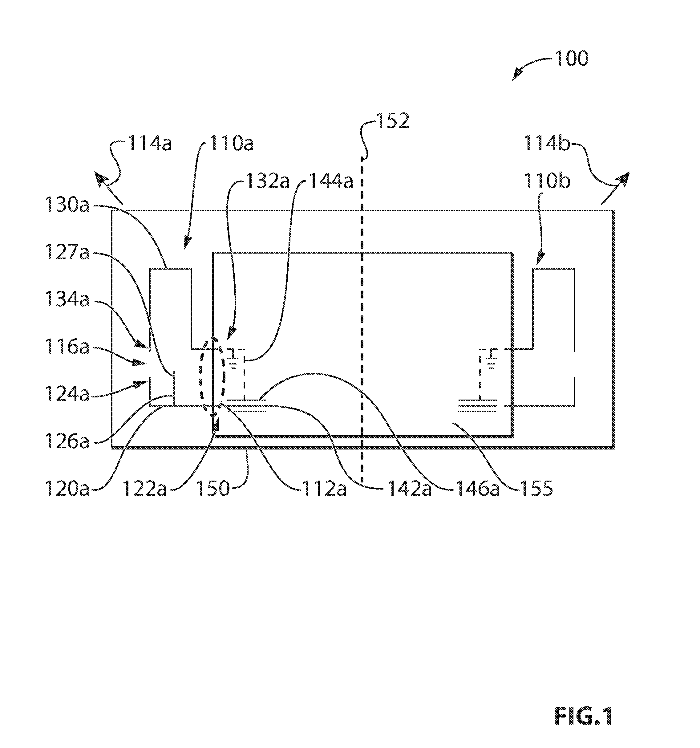
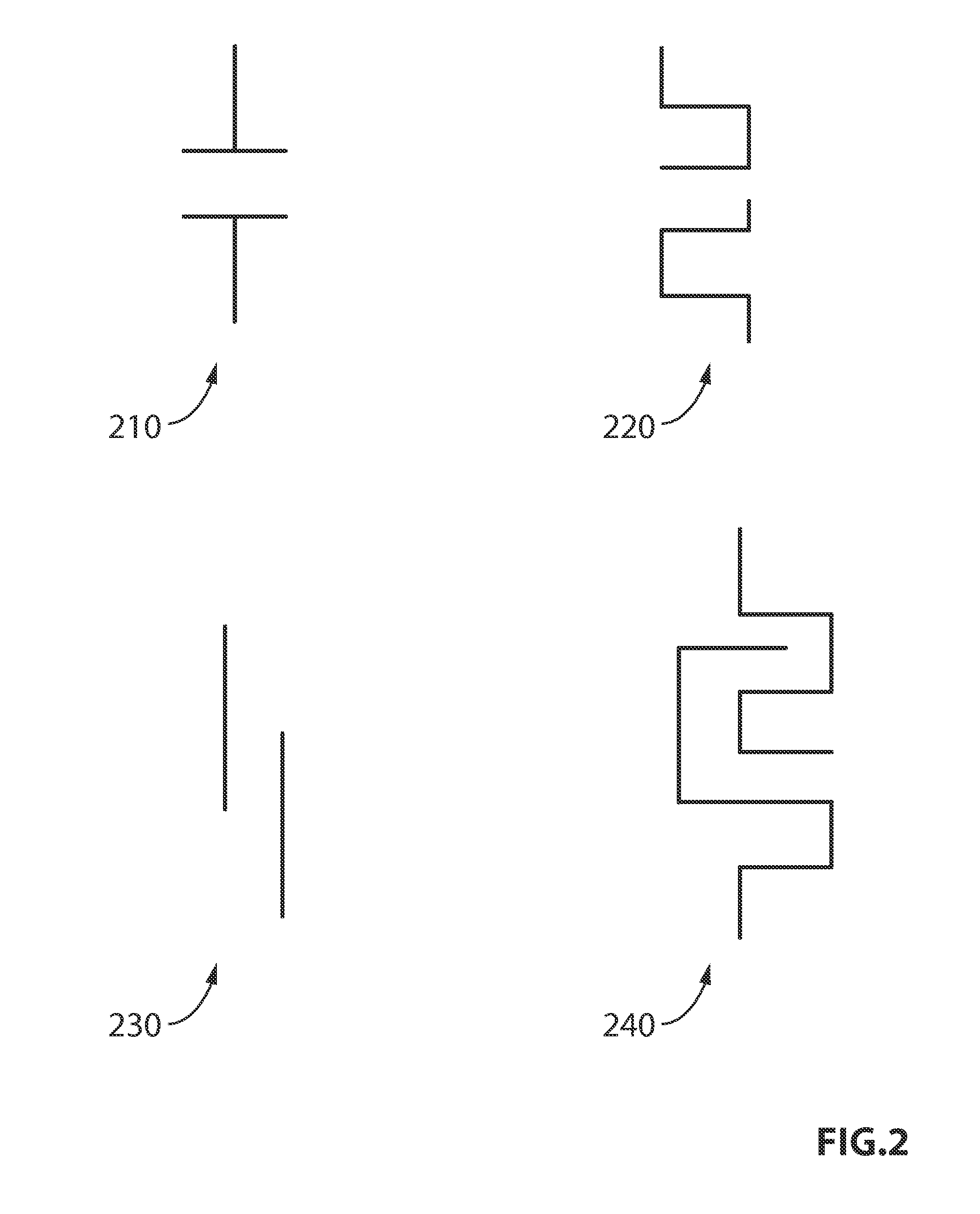
An antenna and multi-antenna system are provided. Each antenna of the system is a mirror image and comprises first and second conductive elements each having a first end and a second end portion, the second end portions being capacitively coupled to each other. Each antenna can be operated as a lower-frequency folded dipole having a series capacitive gap which facilitates electrical lengthening of the antenna, or as a higher-frequency monopole antenna having a parasitic element which facilitates improved bandwidth. The antennas' feedpoints may be placed at opposite corners of a ground plane, and separated by a distance which is less than one quarter of an operating wavelength of the dipole but greater than one quarter of an operating wavelength of the monopole. Locating the feedpoints at the ground plane corners facilitates orthogonal polarization of the two antennas at least in dipole mode. The antennas thus provided exhibit good isolation.

Description

FIELD OF THE INVENTION[0001]The present invention pertains in general to antenna systems and in particular to compact antenna systems having at least one dipole antenna, monopole antenna, or dual-band antenna operating as both a dipole and a monopole.BACKGROUND[0002]Compact antenna systems are desirable for reasons such as portability, cost, and ease of manufacture, and are particularly well-suited for mobile, wireless devices. Interest in compact antenna systems has been further stimulated by the use of higher radio frequencies, for example UHF and higher, which allow for antenna lengths significantly less than 1 centimetre, and by the development of lithographic techniques which allow for antenna systems to be printed directly onto circuit boards or device housings with small form factors at low cost.[0003]However, as the size of portable devices decreases below a quarter of a wavelength of an antenna operating frequency, it becomes challenging to provide for adequate antennas and...

Claims


Application Information

Patent Timeline
IPC IPC(8): H01Q1/36H01Q1/12H01Q9/26H01Q1/48H01Q21/00
CPCH01Q1/243H01Q9/26H01Q5/357H01Q5/0051Y10T29/49826H01Q21/28
Inventor TAN, MACK
Owner NETGEAR INC
Learn More