Speaker

Inactive Publication Date: 2012-12-27
ASEN LAB
View PDF2 Cites 8 Cited by
  • Summary
  • Abstract
  • Description
  • Claims
  • Application Information

AI Technical Summary

Benefits of technology

[0026]A micro speaker according to the present invention has the following advantages.
[0027]First of all, by increasing the magnetic force, the present invention may provide a high sound pressure output.
[0028]Secondly, by decreasing the height of the speaker to a maximum level, the size of the electronic device having the speaker mounted thereon may also be reduced.
[0029]Thirdly, by using a voice coil having a larger diameter, a wire thicker than the related art voice coil may be used. Thus, a high input high output speaker may be fabricated.
[0030]Fourthly, with a decrease in the number of assembly parts, the assembly process of the micro speaker is more simplified. Accordingly, the micro speaker may be fabricated by means of automated production, thereby reducing the fabrication cost.
[0031]Fifthly, since a vent hole unit is formed on a lower surface, heat being generated from the voice coil may immediately discharged, thereby enhancing the durability of the speaker.

Problems solved by technology

Additionally, since the related art voice coil has a diameter of Φ 40 micron, generally, the related art voice coil cannot yield a high output.

Method used


Image

  • Speaker
  • Speaker
  • Speaker

Examples


first embodiment

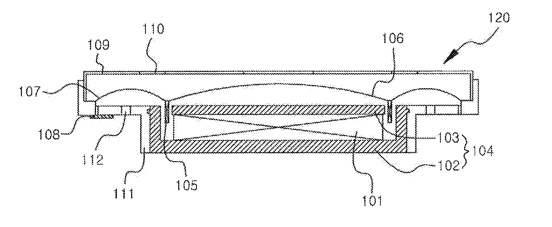
[0039]FIG. 7 illustrates a cross-sectional view of a speaker according to the present invention.

second embodiment

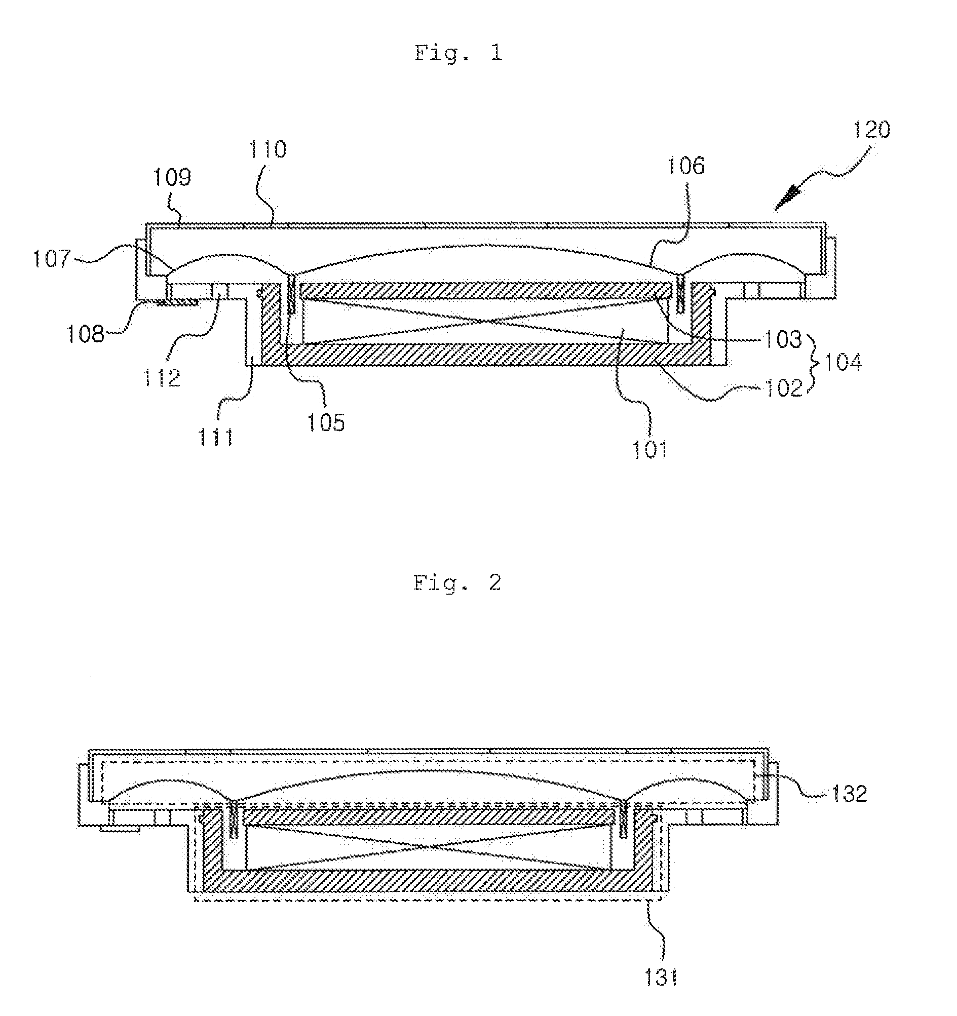
[0040]FIG. 8 illustrates a cross-sectional view of a speaker according to the present invention.

third embodiment

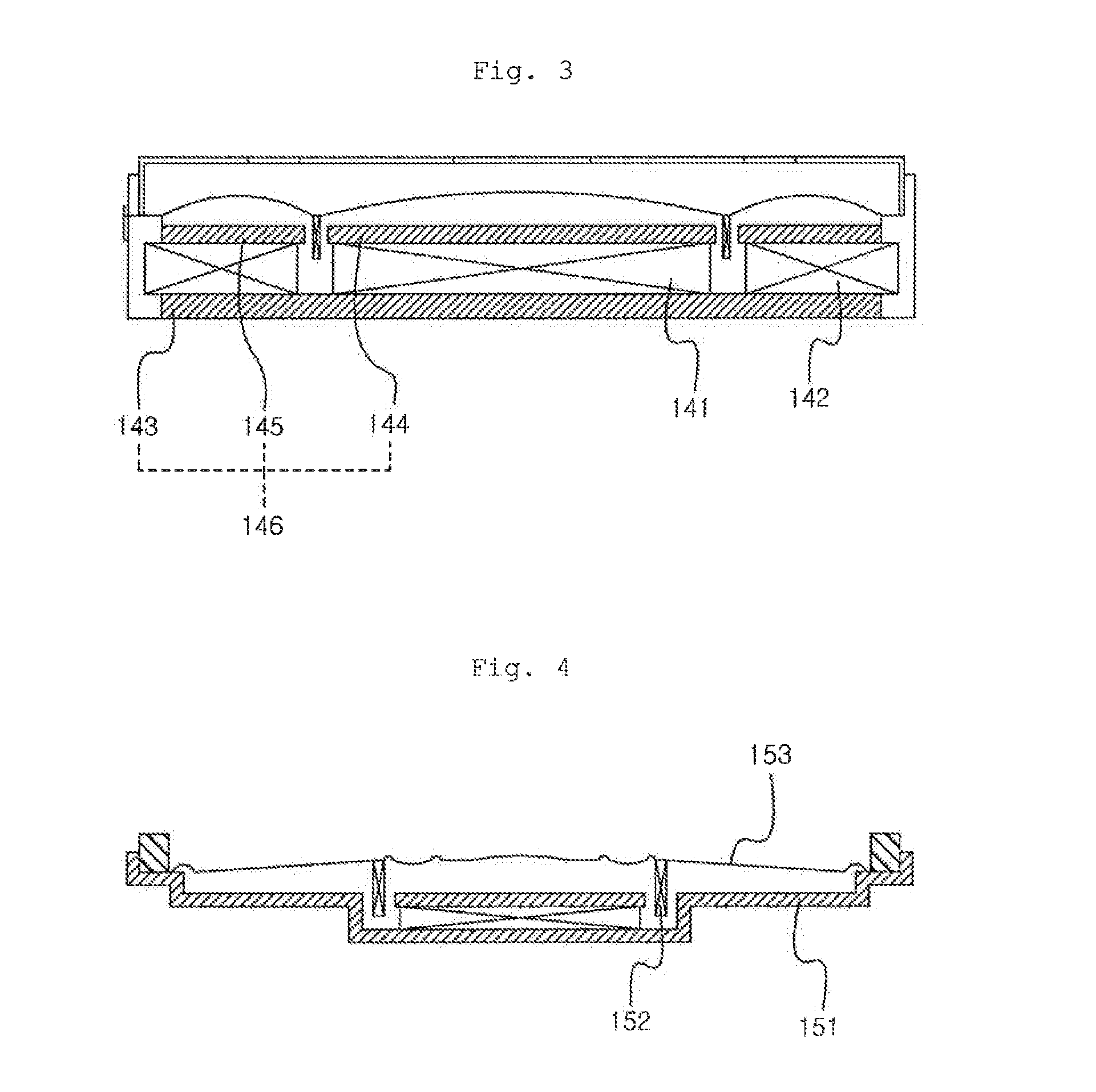
[0041]FIG. 9 illustrates a cross-sectional view of a speaker according to the present invention.

[0042]FIG. 10 illustrates a dispersed perspective view of a speaker according to the first embodiment of the present invention.

[0043]FIG. 11 illustrates a dispersed perspective view of a speaker according to the third embodiment of the present invention.

[0044]FIG. 12 illustrates a graph comparing a performance of the speaker according to the first embodiment of the present invention with a performance of the related art speaker.

[0045]FIG. 13 illustrates a graph comparing a performance of the speaker according to the third embodiment of the present invention with a performance of the related art speaker.


PUM


Abstract

A speaker is disclosed herein. And, in configuring a magnetic circuit of the speaker, unlike the vertical polarity alignment of the related art speaker, the polarities of the magnet are configured to be horizontally aligned, and a vibration system is configured on an inner side surface of the vertically configured magnetic circuit. Accordingly, by having the magnetic circuit encircle the vibration system, unlike in the related art speaker, wherein the height of the speaker corresponds to a sum of the thickness of the vibration system and the thickness of the magnetic circuit, the speaker may be configured only by using the height of the magnetic circuit. Furthermore, by being capable of reducing the height of the speaker, even if the volume of the magnet is being increased, the sound effect of the speaker may be enhanced.

Description

FIELD OF THE INVENTION[0001]The present invention relates to a speaker and, more particularly, to a speaker having a remarkably low height and showing excellent performance.BACKGROUND ART[0002]Generally, a speaker refers to a device that converts electrical signals to sound that can be heard through our ears. Meanwhile, among diverse speakers, a micro speaker refers to a speaker that is suitable for being mounted on small-sized electrical devices or mobile communication devices.[0003]Recently, the electrical devices are becoming smaller in size and more light-weight. Accordingly, the speakers being applied to the electrical devices are required to be even smaller in size and lighter in weight and to show more excellent performance.[0004]FIG. 1 and FIG. 2 illustrate cross-sectional views showing a related art single magnet speaker. As shown in FIG. 1, in the related art speaker, a frame (111) configures an outside form of the speaker (120). A yoke (104), which is configured to provid...

Claims


Application Information

Patent Timeline
IPC IPC(8): H04R3/00H04R9/06
CPCH04R9/06H04R9/025H04R9/02H04R9/04
Inventor KIM, SUK-JOOHEO, DONG-CHOL
Owner ASEN LAB
Why Eureka
Try Eureka