


Quick Research
Generate reliable direction feasibility study reports for your R&D in just a few steps.

Technical Q&A
Discover and master advanced knowledge NOW. Basics, ideas, possibilities, all at once.

Find Solutions
As an expert in R&D theories, this can generate solutions to your technical problems instantly.

Evaluate Feasibility
Analyze your overall solution with one click, know your potential R&D risks in advance.

Monitor Landscape
Get weekly tech updates, stay abreast of the latest tech innovations and key insights.
Cases
An electro-acoustic transducer, piezoelectric technology, applied in piezoelectric/electrostrictive transducers, sensors, electrical components, etc., can solve the problems of increased distortion, sound pressure drop, loss, etc. Effect
- Summary
- Abstract
- Description
- Claims
- Application Information
AI Technical Summary
Problems solved by technology
Method used
Image

Examples
Embodiment 1
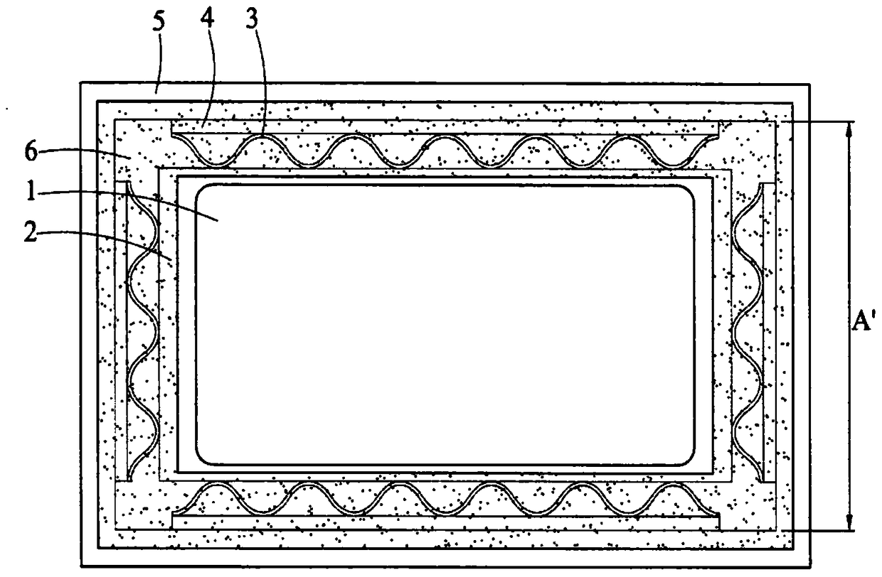
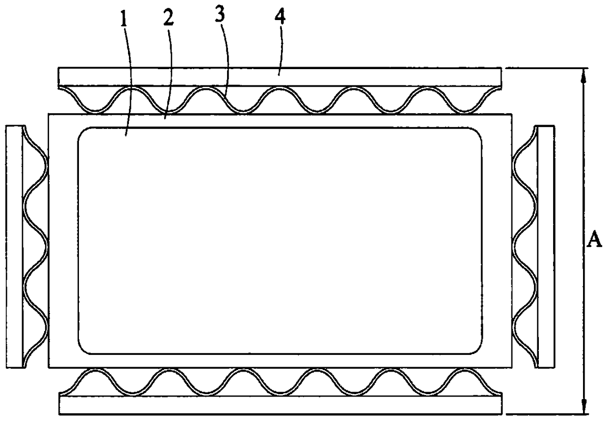
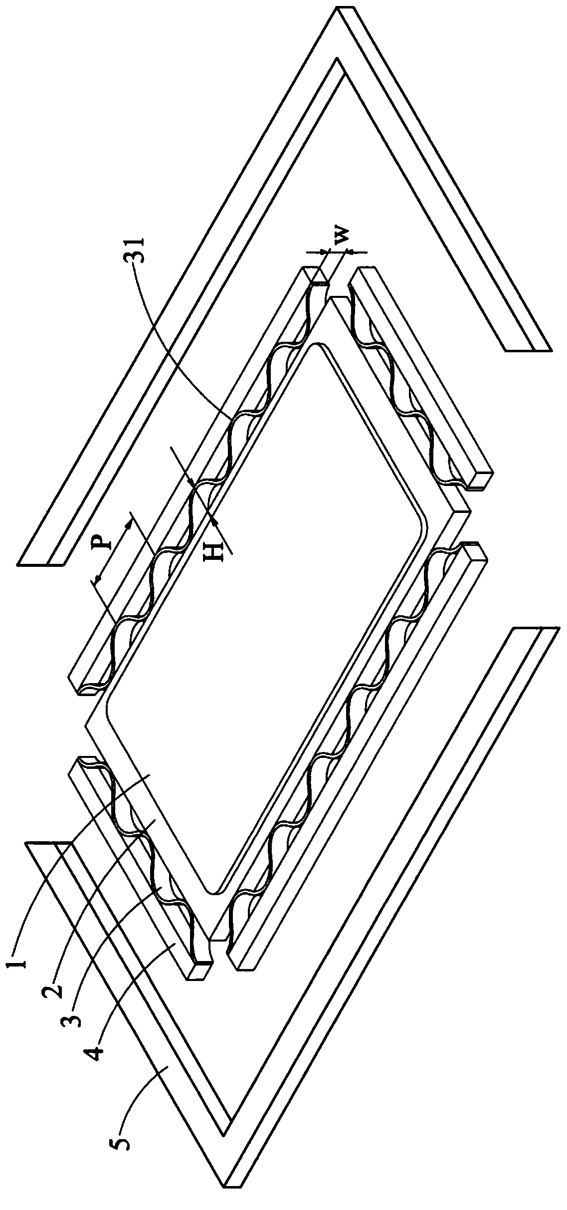
[0044] Embodiment 1, the piezoelectric electroacoustic transducer includes a diaphragm (85mm×42mm×0.1mm), a piezoelectric component (75mm×40mm×0.1mm) attached to the surface of the diaphragm, and is connected around the diaphragm An elastic component with multiple curved structures, a frame surrounding the elastic component, and a buffer body sandwiched between the elastic component and the frame. The distance between the plurality of curved structures is 10 mm, the height of each curved structure is 2 mm, the width is 0.5 mm, and the shape is arc-shaped. The ratio of the projected area of the inner frame of the frame to the combined planar projected area of the diaphragm, the elastic component and the buffer is 1 (that is, no compressive stress is applied). The test electrical parameter is 10Vrms, and the microphone receiving distance is 10cm. The sound pressure level (level) of embodiment 1 and the test result of total harmonic distortion are respectively as Figure 4A...
Embodiment 2
[0045] Embodiment 2: The difference from Embodiment 1 is that the width of the curved structure is 1 mm. The sound pressure level of embodiment 2 and the test result of total harmonic distortion are as Figure 4A and Figure 4B , Figure 5A and Figure 5B , Figure 6A and Figure 6B , Figure 7A and Figure 7B shown.
Embodiment 3
[0046] Embodiment 3: The difference from Embodiment 1 is that the width of the curved structure is 2mm. The sound pressure level of embodiment 3 and the test result of total harmonic distortion are respectively as Figure 4A and Figure 4B shown.
PUM
 Abstract
Description
Claims
Application Information
 - R&D Engineer
- R&D Manager
- IP Professional
- Industry Leading Data Capabilities
- Powerful AI technology
- Patent DNA Extraction
Browse by: Latest US Patents, China's latest patents, Technical Efficacy Thesaurus, Application Domain, Technology Topic, Popular Technical Reports.
© 2024 PatSnap. All rights reserved.Legal|Privacy policy|Modern Slavery Act Transparency Statement|Sitemap|About US| Contact US: help@patsnap.com