Eureka AIR delivers breakthrough ideas for toughest innovation challenges, trusted by R&D personnel around the world.

Circuit breaker

a circuit breaker and circuit technology, applied in the field of circuit breakers, can solve the problems of circuit interruption, difficult to minutely adjust the reactive bending amount and the rotation distance of the cross bar, and the difficulty of interrupting the circuit, so as to reduce the probability of error occurrence, improve the effect of productivity, and save costs

Inactive Publication Date: 2012-12-27
LSIS CO LTD
View PDF16 Cites 6 Cited by
  • Summary
  • Abstract
  • Description
  • Claims
  • Application Information

AI Technical Summary

Benefits of technology

The present invention provides a circuit breaker with a fixed contactor and a movable contactor that can automatically adjust the gap between the pressing member and the cross bar, which is important for determining the time delay operating characteristic of the circuit breaker. This eliminates the need for manual adjustment, improves productivity and reduces the likelihood of errors, resulting in a higher quality circuit breaker.

Problems solved by technology

As a result, a switching mechanism operates to convert a state of the electrical circuit into an open state, thereby interrupting the circuit.
Therefore, it is difficult to minutely adjust the reactive bending amount and the rotation distance of the cross bar, unless the components are replaced.
This may cause the circuit to be interrupted even in a state of an over-current such as an initial driving current.
On the contrary, if the gap between the bimetal and the cross bar is too large, the circuit breaker may have trip time delay, or may not be tripped.
This may cause an over-current to be supplied to the circuit, resulting in damages of the circuit.
Therefore, when considering the number of types of bimetals and heaters, it is impossible to implement a constant gap and to satisfy the time delay operating characteristic with respect to an over-current in a single circuit breaker.
However, since the aforementioned gap control is manually performed, an error occurs according to each operator.
Furthermore, even if the same operator performs the gap control, an error may occur according to each product.
Furthermore, if the process is manually performed, it takes a lot of time to perform the gap control.
This may lower the productivity.

Method used


Image

  • Circuit breaker
  • Circuit breaker
  • Circuit breaker

Examples


Embodiment Construction

[0037]Description will now be given in detail of the exemplary embodiments, with reference to the accompanying drawings. For the sake of brief description with reference to the drawings, the same or equivalent components will be provided with the same reference numbers, and description thereof will not be repeated.

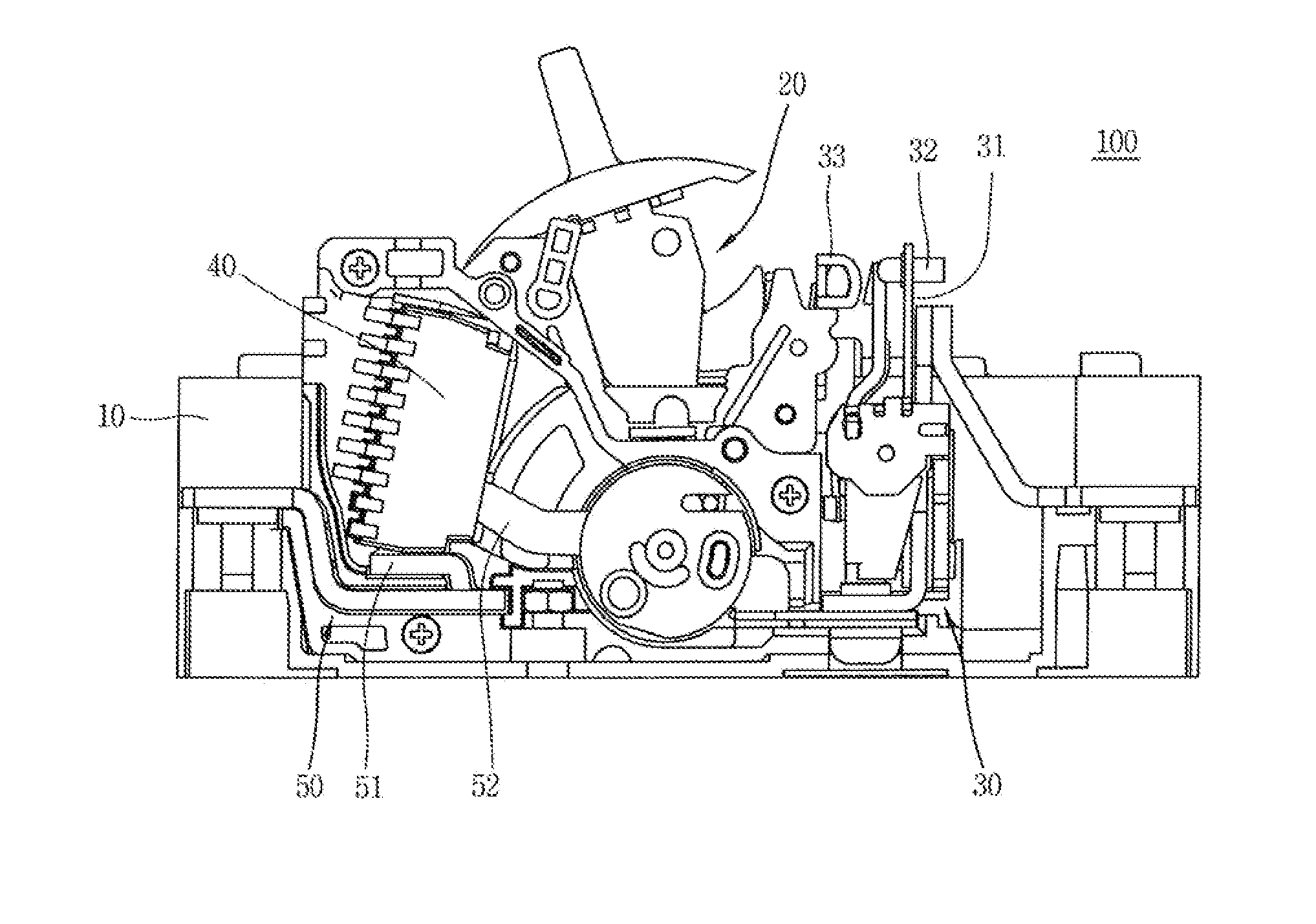
[0038]FIG. 1 is a schematic view of a circuit breaker according to the present invention.

[0039]Referring to FIG. 1, a circuit breaker 100 includes a case 10 configured to accommodate components therein. The case 10 is molded by an insulating material, and is configured to insulate the inside from the outside. Such structure is general, and thus its detailed explanations will be omitted.

[0040]In the case 10, provided are a switching mechanism 20 configured to turn on / off an electrical circuit, a terminal part 50 including a fixed contactor 51 and a movable contactor 52 to which power and a load are connected, respectively, a detection mechanism 30 configured to detect an ab...


PUM


Abstract

A circuit breaker includes: a bimetal bent by heat generated from a conductive current; a pressing member coupled to an upper part of the bimetal; a cross bar spaced from the pressing member by a prescribed gap, and configured to contact the pressing member and to rotate by being pressed when the bimetal is bent; and a switching mechanism operated by rotation of the cross bar, and configured to separate a movable contactor from a fixed contactor, wherein a coupling hole for coupling the pressing member is provided at an upper part of the bimetal, and wherein the pressing member is bonded to the coupling hole after a prescribed gap between the pressing member and the cross bar has been determined by apply of a current when the pressing member is in a state of being freely movable in the coupling hole.

Description

CROSS-REFERENCE TO RELATED APPLICATION[0001]Pursuant to 35 U.S.C. §119(a), this application claims the benefit of earlier filing date and right of priority to Korean Application No. 10-2011-0061955, filed on Jun. 24, 2011, the contents of which is incorporated by reference herein in its entirety.BACKGROUND OF THE INVENTION[0002]1. Field of the Invention[0003]The present disclosure relates to a circuit breaker including a detection mechanism having a structure for automatically setting a gap between a bimetal and a cross bar with respect to a time delay operating characteristic, the detection mechanism for detecting an accidental current and interrupting a circuit.[0004]2. Background of the Invention[0005]A circuit breaker serves to open or close a load in an electric power substation or on an electrical circuit line, etc., or to interrupt a current when an accident such as a ground fault or a short-circuit current occurs. The circuit breaker converts a state of an electrical circuit...

Claims


Application Information

Patent Timeline
Patent Type & Authority Applications(United States)
IPC IPC(8): H01H3/00
CPCH01H9/34H01H71/522H01H71/16H01H69/01
Inventor KIM, WOONG JAE
Owner LSIS CO LTD
Why Eureka
Eureka Blog
Learn More